KSwitch D1 UGPD Unmanaged Gigabit PoE Ethernet Switch - Preliminary User Guide, Rev. 0.9
// 21
4.1.3.
DC Terminal Block
4.1.3.1.
DC-IN
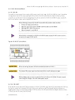
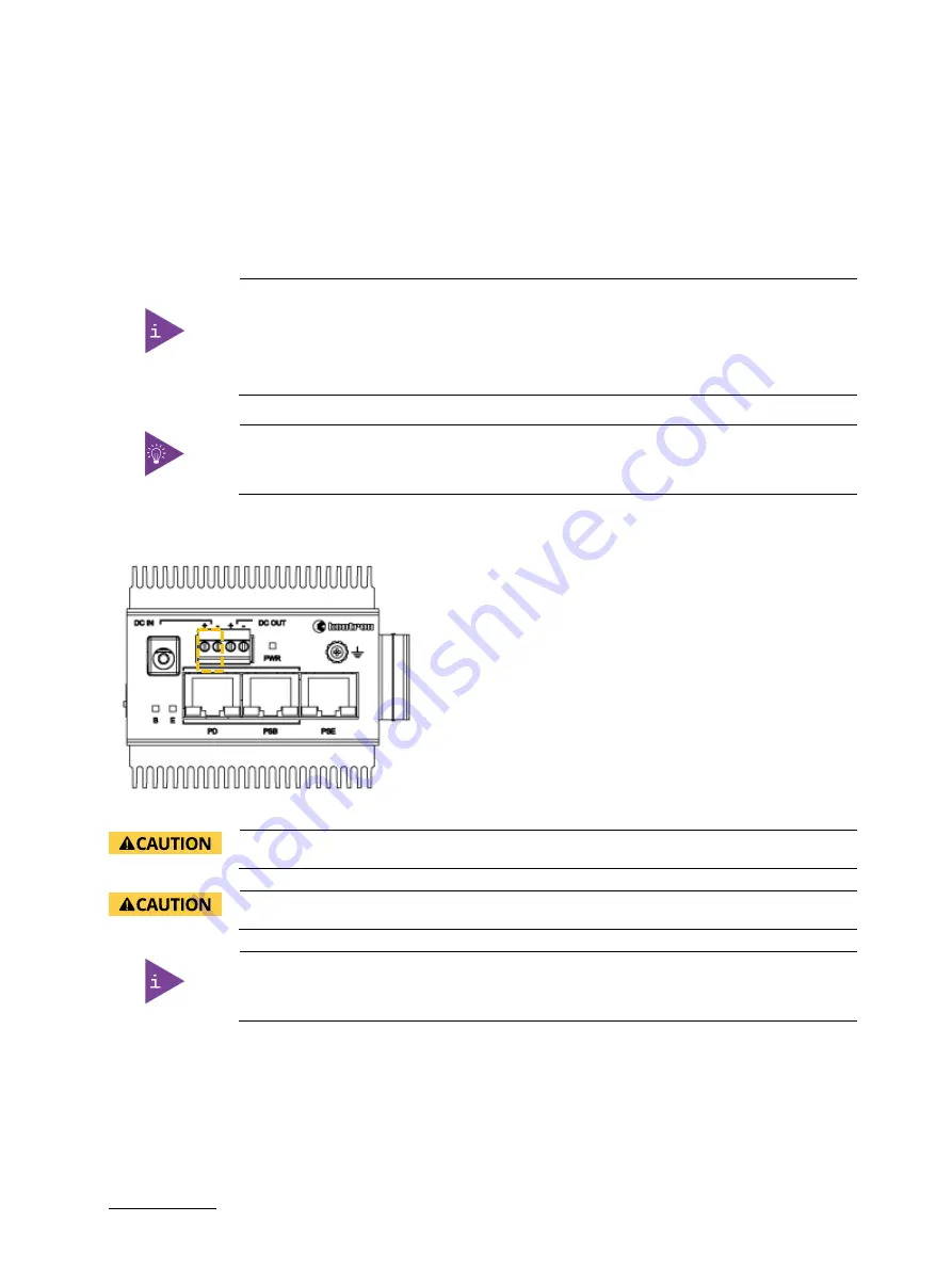
The switch can be powered from an external DC power supply (input range: 24 VDC to 48 VDC) by insert the positive
and negative wires into the corresponding DC-IN contacts on the DC terminal block and tighten the wire-clamp
screws to prevent the wires from loosening. When DC-IN is connected to a 24 VDC to 48 VDC DC power supply, DC-
OUT can be used as a power line to supply 12 VDC and 1 A.
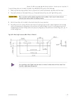
When attaching power wires to the DC terminal block’s power contacts consider:
•
DC terminal block pitch, 3.81 mm
•
Wire size range: Solid wire: 16~28 AWG and Stranded wire: 16~28 AWG
•
Wire length 3 m (9.84 ft.) maximum
•
Wire strip length 7 mm (0.28 in)
When DC-IN is connected to a 24 VDC to 48 VDC DC power supply, DC-OUT can be used as a
power line to supply 12 VDC and 1 A.
Figure 5: DC-IN, DC Terminal Block
When connecting the power follow the indicated polarity for DC-IN +/-.
The external DC power supply must be connected to a well-fused power supply.
With multiple power sources connected to the switch, the switch utilizes the power supply
with the higher voltage or the most stable power supply.
4.1.3.2.
DC-OUT
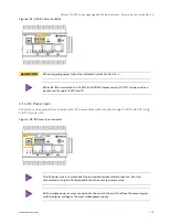
When the DC terminal block’s DC-IN is connected to a 24 VDC to 48 VDC supply the DC terminals blocks’s DC-OUT may
be used as a power line to supply 12 VDC and 1 A to an external device. Insert the external device’s positive and
negative power wires into the corresponding DC-OUT contacts on the DC terminal block and tighten the wire-clamp
screws to prevent the wires from loosening.


