background image

S&C Instruction Sheet 659-520   

49

Maintenance

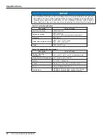
Table 12. Torque Requirements

Assembly

Part

Hardware

Tool

Torque 

[N-M]

Torque 

[Ft-Lbs]

Inverter Pole

Ground Wire

M6 Hex Nut

11-mm Socket

9 .5

7

Ground Bus

M6 Hex Nut

11-mm Socket

9 .5

7

Shorting Bus

M10 Flange 
Nut

15-mm Socket

54 .2

40

Typical Bus

M10 Flange 
Nut/Bolt

15-mm Socket

54 .2

40

Ac Connection

M10 Flange 
Bolt

15-mm Socket

54 .2

40

Typical Bus Connections

N/A

M10 Flange 
Nut/Bolt

15-mm Socket

54 .2

40

Inductor/Cabinet Fans

Terminal Blocks M4 Terminals

Slot Driver

1 .7

1 .25

Dc Blowers

Terminal Blocks M4x12 Screw

3-mm Hex

1 .1

0 .8

Circuit Breaker Terminal 
Block

Terminal Blocks M3 Terminals

Slot Driver

0 .5

0 .4

Circuit Breaker

Bus Tabs

M10 Bolt

8-mm Hex

27 .1

20

EMI Filter Board

Positive Leads

M10 Flange 
Nut

15-mm Socket

13 .6

10

Ground Studs

M6 Hex Nut

11-mm Socket

9 .5

7

Input Box

CT PCB 
Terminals

10-32 Hex Nut 3/8-inch 

Socket

3 .5

2 .6

Capacitor 
Terminal Block

Terminal 
Screws

#2 Phillips

3 .9

2 .9

Relay Block 
Terminals

8-32 Screw

#2 Phillips

2 .2

1 .6

Islanding Tray

CT Terminal 
Block

#10-32 
Terminals

Slot Driver

2

1 .5

Terminal Blocks M4 Terminals

Slot Driver

1 .7

1 .25

PLC

M3 Mounting

#1 Phillips

1 .1

0 .8

Resistor Tray

Contactor - 
Power

M4 Studs

7-mm Socket

1 .4

1

Contactor - Coil M3 Studs

5 .5-mm 
Socket

0 .5

0 .4

Resistor 
Connections

M5x10 Screw

3-mm Hex

3 .9

2 .9

Dc Blower Terminal Block

Terminal Blocks M3 Terminals

Slot Driver

0 .5

0 .4


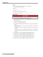
Verify that all accessible electrical control connections are tight (using a screw- 
driver).

Controls


Open the top of the control assembly box and clean the control board with a 
vacuum, if needed.


Verify there is no unusual particulate or fungal growth. If there is, take pictures and 
report it to S&C Electric Company for further evaluation.


Close and re-fasten the top of the control assembly box.


Remove the CompactFlash card and replace it with the new one.  

Summary of Contents for PureWave SMS-250

Page 1: ...ns 3 Replacement Instructions and Labels 3 Location of Safety Labels 4 Safety Precautions 5 Components and Controls Enclosure 6 LCD Screen 6 Dead Front Access Panels 7 Inner Components 7 User Interface 8 Control Assembly 9 Inverter 9 Ac and Dc Circuit Breakers 10 EMI Filters 11 Cable Termination Area 11 Fuses 12 Service Shelf 12 Radio Provisions 14 Human Machine Interface 14 HMI Program 15 Operati...

Page 2: ...losure where they can be easily retrieved for future use Proper Application WARNING The equipment in this publication must be selected for a specific application The applica tion must be within the ratings furnished for the equipment Refer to S C General Brochure 659 G358 for the S C PureWave SMS 250 Storage Management System Failure to do so may result in damage of the equipment Warranty The warr...

Page 3: ...ortant procedures or requirements that can result in product or property damage if instructions are not followed Following Safety Instructions If you do not understand any portion of this instruction sheet and need assistance contact your nearest S C Sales Office or S C Authorized Distributor Their telephone numbers are listed on S C s website sandc com Or call S C Headquarters at 773 338 1000 in ...

Page 4: ... Labels A C C C B B Symbols and Terminal Markings The symbol represents the power on button When the button with the symbol is pressed the breaker places the equipment into a fully powered state Equipment grounding conductor The symbol represents the power off button When the button with the symbol is pressed the breaker disconnects the load side from the power source The dc breaker disconnects th...

Page 5: ... should be sufficient to limit the Ground Potential Rise step voltage and touch voltage to acceptable limits as determined by the util ity s practices and the National Electric Safety Code 9 ENERGIZED COMPONENTS Always consider all parts live until de energized locked open and tested 10 ADDITIONAL CONNECTIONS The user should not attempt to connect any additional logic controls or power connections...

Page 6: ...nclo sure Vents for air flow are located on the back See Figure 1 Figure 1 Front and rear view of the PCS enclosure LCD Screen A four line 40 character liquid crystal display shall be mounted on the control panel protected by a clear plastic window The display shall indicate status information such as voltages ac currents ac power ac vars ac battery voltage dc inverter state operating mode and act...

Page 7: ...rting from the top panel to the bottom panel Use a 2 Phillips screwdriver for the two screws at the top of each panel and a 13 mm socket wrench for the side flange nuts Refer to Figure 34 on page 46 for an illustration of the dead front access panel removal procedure Inner Components DANGER Before removing the dead front access panels make sure that the PCS is de energized to avoid serious injury ...

Page 8: ...cally to the system via Human Machine Interface HMI mode PRE CHARGE This key lock is used when any work or maintenance requires the inverter to be de energized When the inverter stop pushbutton is pressed and the pre charge key is turned to the OFF position ac and dc circuit breakers are open the inverter bridge will discharge to a safe level in 5 minutes WARNING Capacitors in the PCS may have res...

Page 9: ...rvice and mainte nance personnel use NOTICE Access and use of the control assembly should be done by authorized personnel who are trained in servicing the PCS Figure 6 Control assembly inputs and indicators Inverter The inverter assembly consists of a three phase four quadrant inverter that converts the dc power to ac power It creates the three phase output from the dc battery bus Insulated gate b...

Page 10: ...Dc Circuit Breaker CB2 The dc circuit breaker can automatically isolate the PCS from the battery in the event of a Trip Offline alarm or inverter stop The circuit breaker is rated at 400 A See Figure 8 for the location of the dc circuit breaker NOTICE A few operating controls on the ac and dc circuit breakers are located inside the PCS However unless otherwise specified these controls should only ...

Page 11: ...ters Figure 9 Location of EMI filters Cable Termination Area The ac and dc cable termination area is located inside the enclosure at the bottom left corner This user accessible termination area shall include terminals for connecting the utility source cables and the dc terminals for connecting the battery pack cables See Figure 10 for the location of the cable termination area Cable termination ar...

Page 12: ...ssist personnel in servicing or monitoring the unit The shelf top and brackets are bolted on the inside of the enclosure door See Figure 12 Shelf top Shelf brackets Figure 12 Location of stowed shelf top and brackets Shelf Assembly STEP 1 Using a 13 mm hexagonal wrench unbolt the four flange nuts located at the corners of the shelf top a Unbolt the nuts holding the brackets The nuts will be used t...

Page 13: ...e shelf top to the door The shelf is now ready for use See Figure 15 Figure 15 Shelf installed NOTICE Do not close the enclosure door when the shelf is installed The shelf will need to be disassembled after servicing is complete Failure to do this can result in damage to the equipment The service shelf can also be used for removing and replacing the IGBT inverter pole assemblies inside the PCS Ref...

Page 14: ...ld be set to 255 255 255 0 The default gateway can be the same as the IP address Domain Name System DNS is not needed After the user computer network settings are configured the user can attempt to connect to the HMI control by doing the following Using an Ethernet cable connect the computer to the WEB SERVER CONNECTION port on the user interface Open the Firefox Web browser When prompted provide ...

Page 15: ...this indicates that the circuit breaker is closed If the circuit breaker is green this indicates that the circuit breaker is open The oneline screen also shows the inverter utility and battery information The green box to the left shows the alarm and communication status system state and current real and reactive power output values If the alarm types and or communication items are green there are...

Page 16: ...gs and Digitals Figure 19 is the Alarm Status menu screen which displays the status of the alarms In addition the user can place the mouse over the listed alarm to display a tool tip pop up window that provides a description of what the alarm is and the suggested troubleshoot ing actions to clear it Figures 20 and 21 on page 17 show the Analogs and Digitals status menu screens respectively Figure ...

Page 17: ...S C Instruction Sheet 659 520 17 Figure 20 The Analog statuses window Figure 21 The Digital statuses window Components and Controls ...

Page 18: ... levels during any time of the week As seen in Figure 22 the user can place the mouse over the Power Scheduling tab to display the power scheduling drop down menu items Profile Setup and Week Setup Figures 23 and 24 on page 19 show the screen of these menu items respectively Figure 22 The Power Scheduling drop down menu Figure 23 The Profile Setup window Components and Controls ...

Page 19: ... Command and Control tab enables the user to command real or reactive power to the load It also allows the user to choose different modes of operation such as peak shaving renewable smoothing schedule follow or islanding See Figure 25 Figure 25 The Command and Control window Components and Controls ...

Page 20: ...roperly As seen on Figure 26 the user can place the mouse over the SCADA Test tab to dis play the SCADA test drop down menu items AI Analog Inputs AO Analog Outputs DI Digital Inputs and DO Digital Outputs Figures 27 and 28 29 on page 21 and 30 on page 22 show the respective screens of these menu items Figure 26 The SCADA TEST drop down menu Figure 27 The Analog Inputs window Components and Contro...

Page 21: ...S C Instruction Sheet 659 520 21 Components and Controls Figure 28 The Analog Outputs window Figure 29 The Digital Inputs window ...

Page 22: ...place the mouse over the Configuration tab to dis play the configuration Field Parameters and Communication drop down menu items Figures 32 and 33 on page 23 show the screen of these menu items respectively Plac ing the mouse over each parameter in these figures reveal a tool tip pop up window that describes what the parameter means Figure 31 The Configuration drop down menu Components and Control...

Page 23: ...S C Instruction Sheet 659 520 23 Figure 32 The Field Settings window Figure 33 The Communication Setup window Components and Controls ...

Page 24: ...wer during peak demand times Power Scheduling Dispatches power at a given time for a certain duration on any day of the week Renewable Smoothing Limits the rate of change in power from the renewable source by charging discharging the battery Voltage Regulation Mitigates voltage fluctuations by generating leading lagging reactive power vars States Listed in Table 2 are the five operating states of ...

Page 25: ... remain unaffected Trip Offline Indicates a problem that needs attention and will affect the proper operation of the system The system will not operate and the ac and dc circuit breakers will open Basic Operation The following describes how the user can operate the PureWave SMS 250 system using HMI SCADA Disable and SCADA SCADA Enable modes Toggle the SMS CONTROL switch on the user interface to se...

Page 26: ...ing panel must be installed Automatic Islanding In this mode the PureWave SMS 250 system will command the island circuit breaker open by closing the island circuit breaker open contact when it sees a Utility Disturbance Monitor UDM overvoltage or a UDM undervoltage event or an overfrequency or underfrequency event for the time specified on the Configura tion Field Parameters HMI screen When the is...

Page 27: ...nding with Open Transition Return In this mode the utility has control of the opening and closing of the island circuit breaker When an island is detected the utility commands the island circuit breaker open When the PureWave SMS 250 system sees a UDM overvoltage or a UDM undervoltage or an overfrequency or underfrequency and the Start Island SCADA control point is set the PureWave SMS 250 system ...

Page 28: ...and When the island circuit breaker feedback voltage 24 V goes away indicating that the island circuit breaker is open the PureWave SMS 250 system will run in the Island mode providing power to the islanded load When the Stop Island command is received and the utility is providing power at a normal voltage and frequency the PureWave SMS 250 system will synchronize to the utility and command the is...

Page 29: ...en on the Command Control HMI screen under the Islanding Control menu click on the Stop Island radio button for the PureWave SMS 250 system to go to the Ready state SCADA The user can select the DNP Point 3 StopIsland to pulse on a request for the PureWave SMS 250 system to go to the Ready state Alarm List and Troubleshooting Tips The PureWave SMS 250 system contains an extensive self diagnosis sy...

Page 30: ...ts contact S C Electric Company SELF Dc Breaker Closed Indicates the dc circuit breaker is closed and has been closed for 300 ms Troubleshooting Tip No action is required SELF Dc Pre charge Voltage High Indicates the dc pre charge voltage is above what is expected causing problems with charging the dc link Troubleshooting Tip Contact S C Electric Company SELF Dc Pre charge Voltage Low Indicates th...

Page 31: ... the PureWave SMS 250 system is following a var command from the local control Troubleshooting Tip No action is required SELF Power Factor Control Indicates the PureWave SMS 250 system is maintaining a power factor Troubleshooting Tip No action is required SELF Reset Command Indicates a reset has been sent Troubleshooting Tip No action is required SELF SCADA Control Selected Indicates the control ...

Page 32: ... voltage and frequency are good Troubleshooting Tip No action is required SELF VAC Constant Voltage Indicates the PureWave SMS 250 system is following a constant voltage command Troubleshooting Tip No action is required SELF VAC Droop Control Indicates the PureWave SMS 250 system is following a voltage droop curve Troubleshooting Tip No action is required SELF Warning Alarms These alarms indicate ...

Page 33: ...at the data to see if the low voltage is on the island or the PureWave SMS 250 side If it is on the island side one at a time check the island feedback fuses in the PCS enclosure If the fuses are all good check any fuses that are located between the island feedback source and the PureWave SMS 250 system If the low voltage is on the PureWave SMS 250 side the conductivity of the island circuit break...

Page 34: ...F IGBT 1 Thermistor Shorted Indicates the IGBT 1 thermistor is shorted resulting in very high temperature readings Troubleshooting Tip Contact S C Electric Company SELF IGBT 2 Current Limit Indicates IGBT 2 is working at its limit Troubleshooting Tip Replace current sensor power supply or contact S C Electric Company SELF IGBT 2 Over Temperature Warning Indicates IGBT 2 is too hot This alarm is us...

Page 35: ...c Company SELF IGBT 3 Thermistor Shorted Indicates the IGBT 3 thermistor is shorted resulting in very high temperature readings Troubleshooting Tip Contact S C Electric Company SELF PS1 24VDC Under Voltage Indicates the power supply feeding off the dc bus is not working Troubleshooting Tip Contact S C Electric Company SELF PS2 24VDC Under Voltage Indicates the power supply feeding off the utility ...

Page 36: ...edback fuses If the fuses are all good then the conductivity of the dc circuit breaker CB1 could be the problem If this is the case contact S C Electric Company SELF Dc Link Over Voltage Indicates the battery voltage is higher than the maximum allowed battery voltage which can damage the battery Troubleshooting Tip If the auto reset has locked out reset the alarm AUTO Dc Link Under Voltage Indicat...

Page 37: ...verter will respond based on the Over Frequency settings To change the sensitivity time delay on or the frequency threshold can be changed SELF Over Voltage Indicates the line to line voltage at any of the three phases at the inverter ac connection is above the overvoltage threshold Troubleshooting Tip The inverter will respond based on the voltage settings To change the sensitivity time delay on ...

Page 38: ...e inverter ac connection is above the Very Overfrequency threshold Troubleshooting Tip The inverter will respond based on the Very Overfrequency settings To change the sensitivity time delay on or the frequency threshold can be changed SELF Very Over Voltage Indicates the line to line voltage at any of the three phases at the inverter ac connection is above the Very Overvoltage threshold Troublesh...

Page 39: ...ins contact S C Electric Company SELF Battery Cell Over Voltage Indicates a battery cell has overcharged and continued operation could be dangerous Troubleshooting Tip The battery cell may equalize its charge over time If the cell does not equalize and the alarm remains contact S C Electric Company SELF Battery Cell Under Voltage Indicates a battery cell has discharged beyond normal operating rang...

Page 40: ...oting Tip The user can issue a reset to clear this alarm The system should then be watched to determine whether the original alarm comes back If it does troubleshoot the alarm that is causing this alarm not this alarm MANUAL BMS Requested Trip Offline Indicates the BMS has opened a breaker to stop the inverter from charging or discharging the battery Troubleshooting Tip Check F8 This is used to pr...

Page 41: ...a utility transient caused the alarm Check the broken thermistor alarms for all phases If they are clear the system can be reset If the broken thermistor alarms are present do not reset the alarm Contact S C Electric Company MANUAL Inverter Stop Indicates the inverter has stopped operating The battery and utility are disconnected Troubleshooting Tip Twist the inverter stop button clockwise to clea...

Page 42: ...eal Reactive Power 263 kW 263 kVA Secondary Voltage 380 Vac directly 400 415 or 480 Vac using an auto transformer Frequency 50 or 60 Hz Dimensions single enclosure 36 W 36 L 80 H inches 915 915 2032 mm Weight 2 000 lbs 907 2 kg Table 11 Environmental Specifications Description Value or Range Ambient Operating Temperature 40 F to 104 F 40 C to 40 C without de rating Storage Ambient Temperature 49 F...

Page 43: ...rt Monitoring Center at 888 762 1100 Annual Maintenance Checklist The PCS requires a minimal amount of maintenance to help ensure high system reli ability and efficiency The following checklist can be used as a reference to assist in properly maintaining the unit s DANGER Make sure the PCS is de energized before performing maintenance on the equipment Taking this necessary step will minimize serio...

Page 44: ...s open Use a meter with insulated leads that will not short to the dead front for the follow ing steps Verify there is line to line ac voltage from the bottom of F4 ac fuse to the bottom of F5 ac fuse Verify there is line to line ac voltage from the bottom of F5 to the bottom of F6 ac fuse Verify there is line to line ac voltage from the bottom of F6 to the bottom of F4 Verify there is dc voltage ...

Page 45: ...ac voltage from the bottom of F1 to the bottom of F2 Verify there is no dc voltage from the bottom of F1 to the bottom of F2 Verify there is no ac voltage from the bottom of F4 to the bottom of F5 Verify there is no dc voltage from the bottom of F4 to the bottom of F5 Verify there is no ac voltage from the bottom of F5 to the bottom of F6 Verify there is no dc voltage from the bottom of F5 to the ...

Page 46: ...____________________________________________________________ Check gaskets and seals around the door and the PCS enclosure opening Are the gaskets and seals in good condition YES or NO circle one If no replace the gasket Use S C part number CD 2340 If gasket is not in good condition but not replaced Why Internal Components Inspect door latching mechanisms Make sure the mechanism operates easily an...

Page 47: ...ing noise when the fan is rotating Verify there is no rust visible IGBT Pole Fan 1 Verify the fans spin freely Verify there is no bearing noise when the fan is rotating Verify there is no rust visible IGBT Pole Fan 2 Verify the fans spin freely Verify there is no bearing noise when the fan is rotating Verify there is no rust visible IGBT Pole Fan 3 Verify the fans spin freely Verify there is no be...

Page 48: ...nks For IGBT inverter assembly 2 Replace any damaged components Check for and remove any foreign debris Clean the IGBT pole paying careful attention when cleaning the laminated bus bar Check for signs of thermal or electrical stress as well as discolored components Check capacitors for any signs of damage Clean the large heat sinks For IGBT inverter assembly 3 Replace any damaged components Check ...

Page 49: ...9 5 7 Input Box CT PCB Terminals 10 32 Hex Nut 3 8 inch Socket 3 5 2 6 Capacitor Terminal Block Terminal Screws 2 Phillips 3 9 2 9 Relay Block Terminals 8 32 Screw 2 Phillips 2 2 1 6 Islanding Tray CT Terminal Block 10 32 Terminals Slot Driver 2 1 5 Terminal Blocks M4 Terminals Slot Driver 1 7 1 25 PLC M3 Mounting 1 Phillips 1 1 0 8 Resistor Tray Contactor Power M4 Studs 7 mm Socket 1 4 1 Contacto...

Page 50: ...wo screens down are the main IGBT blowers Verify air flow on all three assemblies The fourth screen down is the inductor fan Verify that it is working properly Close the dc source to supply dc power to the PureWave SMS 250 system With the site facilitator s approval run the PureWave SMS 250 system to verify proper functionality Connect the laptop computer to the Ethernet connection and start the H...

Page 51: ...rd these below Control Mode SCADA Enabled or Disabled ____________________ System State ____________________ Close and padlock all access doors Send the CompactFlash card to S C Electric Company for analysis Annual Maintenance Performed By ____________________________________________ Date ___________________ Maintenance ...

Reviews: