


48
S&C Instruction Sheet 659-520
Power electronic assemblies
□
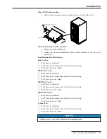
For IGBT inverter pole assembly servicing, install the service shelf in the PCS as
illustrated in Figure 36.
Figure 36. Shelf installation for pole(s) servicing.
□
Remove the three IGBT inverter assemblies using the procedure located at the top
inside of the PCS enclosure door.
For IGBT inverter assembly #1:
□
Replace any damaged components.
□
Check for and remove any foreign debris.
□
Clean the IGBT pole, paying careful attention when cleaning the laminated bus bar.
□
Check for signs of thermal or electrical stress as well as discolored components.
□
Check capacitors for any signs of damage.
□
Clean the large heat sinks.
For IGBT inverter assembly #2:
□
Replace any damaged components.
□
Check for and remove any foreign debris.
□
Clean the IGBT pole, paying careful attention when cleaning the laminated bus bar.
□
Check for signs of thermal or electrical stress as well as discolored components.
□
Check capacitors for any signs of damage.
□
Clean the large heat sinks.
For IGBT inverter assembly #3:
□
Replace any damaged components.
□
Check for and remove any foreign debris.
□
Clean the IGBT pole, paying careful attention when cleaning the laminated bus bar.
□
Check for signs of thermal or electrical stress as well as discolored components.
□
Check capacitors for any signs of damage.
□
Clean the large heat sinks.
□
Replace the three IGBT assemblies (following the instructions located at the
top-inside of the PCS door.
□
Torque the bus connections and components according to Table 12 on the next
page.
Maintenance