background image

15"LCD 4/8-channel H.264 DVR COMBO

34

Wireless

Wireless

Wireless

Wireless network

network

network

network

: The criteria for selection of wireless network include 3G,

2.5G and 2.75G. Press “Enter” to change over between these 3 criteria. Please

make a choice based on your local mobile operator and the network standard

supported by your mobile phone.

Service

Service

Service

Service port

port

port

port

: with a setting range of 1,024—65,535; this port has to be mapped

on the router, and its setup method is the same as the mapping method of the port

in network setup.

For

For

For

For more

more

more

more detailed

detailed

detailed

detailed mobile

mobile

mobile

mobile phone

phone

phone

phone installation

installation

installation

installation and

and

and

and user

user

user

user mannual,please

mannual,please

mannual,please

mannual,please refer

refer

refer

refer to

to

to

to

the

the

the

the Mobile

Mobile

Mobile

Mobile Phone

Phone

Phone

Phone User

User

User

User Mannual

Mannual

Mannual

Mannual in

in

in

in the

the

the

the CD

CD

CD

CD disk

disk

disk

disk

3.7.5

3.7.5

3.7.5

3.7.5 System

System

System

System maintenance

maintenance

maintenance

maintenance

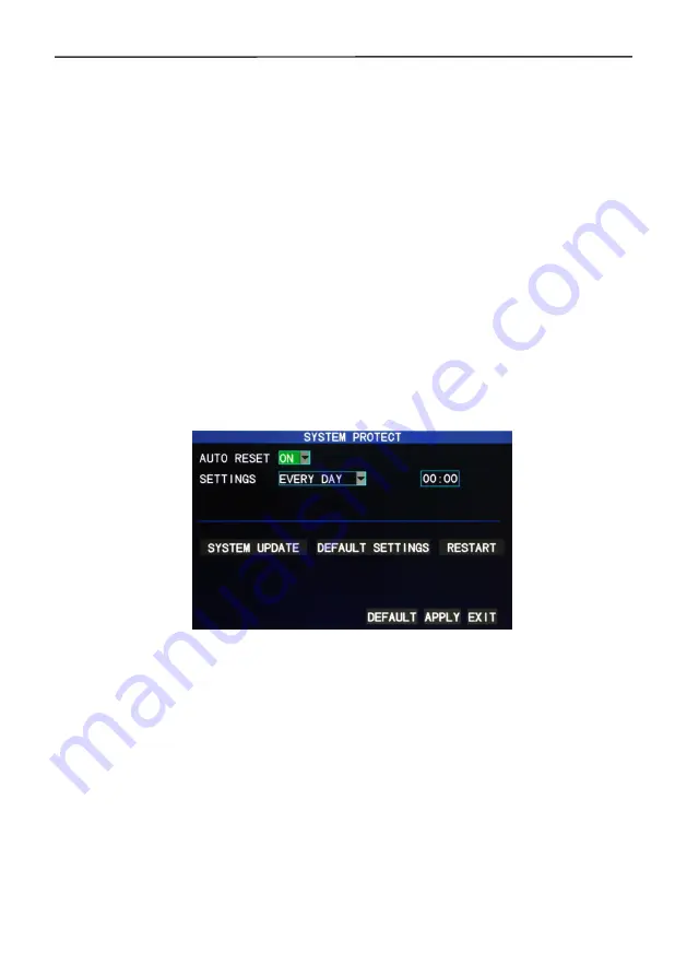
Enter the “System Maintenance” screen from “Main Menu” →“Advanced

Functions”, as shown below:

Automatic

Automatic

Automatic

Automatic maintenance

maintenance

maintenance

maintenance

: When this option is set to “On”, the user can set the

restart frequency and time of this device himself/herself.

System

System

System

System update

update

update

update

: Copy the update file to the root directory of the U-disk, then

insert the U-disk into the USB slot of this unit, and “Enter” this button for system

updating. The screen will display the progress box of system updating until

updating is completed. The power system should not be interrupted during

updating.

Restoration

Restoration

Restoration

Restoration to

to

to

to default

default

default

default settings

settings

settings

settings

: Restore the system parameters to the default

settings.

Restart

Restart

Restart

Restart

: Restart this unit.

Summary of Contents for 20SA-2305A

Page 1: ...1 4 8 channel Embedded Digital Video Recorder ...

Page 2: ... output 11 Chapter 2 Quick installation 12 2 1 Combo installation 12 2 2 Boot 13 2 3 System login 14 2 4 Shortcut menu 14 2 4 1 Main menu 15 2 4 2 Lock 15 2 4 3 Channel switching 15 2 4 4 Video search 15 2 4 5 PTZ Control 15 2 4 6 Mute open volume 16 2 4 7 Manual recording stop recording 16 2 4 8 LCD menu setup 16 Chapter 3 Advanced settings 17 3 1 Main menu 17 3 2 Recording mode 17 3 3 Video sear...

Page 3: ...ance 34 3 7 6 PTZ setup 35 3 7 7 Network setup 35 3 8 Domain name application 38 3 9 Port mapping 43 Chapter 4 DVR network 45 4 1 Functional characteristics 45 4 2 Installation and download of controls 45 4 3 IE log in 46 4 4 Real time preview 46 4 5 Record playback 47 4 6 Recording mode 48 4 7 Alarm setup 48 4 8 PTZ control 49 4 9 Network setup 49 4 10 System setup 50 4 11 Host info 50 Appendix 1...

Page 4: ...and tidy Proper grounding shall be installed during operation DVR should be installed to ensure the proper connectivity with other devices P P P Please lease lease lease buy buy buy buy harddisk harddisk harddisk harddisk from from from from official official official official channel channel channel channel to to to to meet meet meet meet DV DV DV DVR R R R s s s s long long long long time time t...

Page 5: ...ct instruction One piece of SATA harddisk data cables installed in the host One DC12V5A power adapter HDD support already installed and a set of mounting screws One piece of HDD power cable already installed in the host One piece of CD A set of BNC connect cable A set of audio connect cable 1 3 1 3 1 3 1 3 Main Main Main Main f f f features eatures eatures eatures DVR LCD Combo folding installatio...

Page 6: ... BNC Video output 1 channel BNC Audio input output 4 8 channels RCA input 1 channel RCA output Display 1 4 8 channel Multiplex operation Live display recording network transmission recording backup mobile phone surveillance simultaneously Display resolution PAL D1 704 576 NTSC D1 704 480 Recording mode Timer manual motion detection alarm Recording frame rate PAL 25fps NTSC 30fps Recording quality ...

Page 7: ... and protocol 1 RJ 45 10 100M via Ethernet support TCP IP DHCP DNS DDNS NTP etc IE browser Support Client software Support Dual stream Support main and secondary interchange Group play At least support five users online access Multi language Support Mobile phone surveillance Support Windows symbian iPhone and other operation systems SDK package Availabe Mouse interface USB2 0 Backup interface USB2...

Page 8: ...VR power indicator LEFT DVR menu to left REC DVR recording indicator RIGHT DVR menu to right LINK DVR network connection indicator DOWN DVR menu down LCD POWER LCD power switch UP DVR menu up LCD AUTO ESC LCD screen auto adjust exit the menu DISP Display mode option LCD RIGHT LCD menu selection to right MENU DVR main menu LCD LEFT LCD menu selection to left ESC DVR menu exit LCD MENU ENTER LCD mai...

Page 9: ... ALARM Connect alarm switch output the alarm switch output 6 DC12V Connect power supply in DC relay power supply capacity is 1A not short circuit 7 SENSOR 1 8 Connect alarm switch input 4 channel equipment 4 alarm inputs 8 channel equipment 8 alarm inputs 8 G Alarm input common interface Note The figure above is 8 channel DVR back panel 4 channel DVR back panel can only allow 4 channel video input...

Page 10: ...lti split screen Quit shortcut menu Shortcut menu Direction buttons Next on the left and right OK ESC Exit Return MENU Enter the main menu STARTRECStart recording please refer to 2 4 7 for the method STOPREC Stop recording please refer to 2 4 7 for the method Video Search Stop playing Fast backward Fast forward Frame movement F1 F2 Spare key ...

Page 11: ... A PTZ control is available if clicking direction or and icon B There is a volume bar in volume control interface Move mouse to a position and click right button the corresponding volume will be shown in the right side of the volume bar click to exit C The operations like color adjustment can be referred to above volume adjustment 3 If there are many options in the option box click the left button...

Page 12: ...put output output Alarm input close connection Alarm input open connection Alarm output open connection DVR Response output P P P Power ower ower ower Sound and light alarm NC NC NC NC C C C C 47kΩ 12 Infrared alarm DVR ALARM IN 1 2 3 4 5 6 7 8 GND NC NC NC NC C C C C 12 Infra Infrared alarm 47kΩ DVR ALARM IN 1 2 3 4 5 6 7 8 GND ...

Page 13: ...lding i i i installation nstallation nstallation nstallation HDD HDD HDD HDD Installation Installation Installation Installation Harddisk installation must be carried out by technicians to avoid damage to the equipment and harddisk The DVR mainframe must be powered off before operation This equipment supports harddisk with SATA interface Seagate brand harddisk is recommended Installation procedure...

Page 14: ...he DC12V5A power adapter to the power cord socket in back panel and press the power button in front panel the recorder will be on power indicator POWER is on the monitor will display 4 8 channel monitoring image If non formatted harddisk exists in the equipment harddisk formatting information will be shown If boot record mode is on or boot time is in the setting time the system will start automati...

Page 15: ...he mainframe will match automatically when you enter password and different permissions will be given according to different passwords If you want to operate in mainframe menu after password is set the system will display user login interface Equipment Equipment Equipment Equipment code code code code it is just ok to enter equipment code 000000 displayed on right side in corresponding input box T...

Page 16: ...diately password is required to log in if operation to mainframe menu is needed 2 4 3 2 4 3 2 4 3 2 4 3 Channel Channel Channel Channel switching switching switching switching 8 channel DVR can choose eight channel front four channel and back four channel 4 channel DVR can choose to switch 4 channel and one channel 2 4 4 2 4 4 2 4 4 2 4 4 Video Video Video Video search search search search Please ...

Page 17: ...op recording recording recording recording If timing record is on please see Chapter 3 and recording it not set in this period manual recording and timing record is effective When boot record mode is on this function is not available 2 4 8 2 4 8 2 4 8 2 4 8 LCD LCD LCD LCD menu menu menu menu setup setup setup setup Main menu Sub menu picture Definition Brightness Contrast Color temperature Volume...

Page 18: ...ristic of of of of this this this this product product product product is is is is when when when when you you you you move move move move the the the the cursor cursor cursor cursor to to to to any any any any option option option option the the the the prompting prompting prompting prompting message message message message of of of of this this this this option option option option will will wil...

Page 19: ...UALITY QUALITY available in the 3 levels of highest high and normal corresponding to the 3 data stream standards of highest high and medium bit rates A A A AUDIO UDIO UDIO UDIO switching on or off audio recording REC MODE REC MODE REC MODE REC MODE available in the two modes of startup recording and timing recording When When When When powered powered powered powered up up up up starting recording...

Page 20: ...f 15min 30min 45min and 60min 3 3 3 3 3 3 3 3 Video Video Video Video search search search search Enter the Video Search screen from Main Menu Video Search as shown below This unit supports 3 video search modes A A A A Timing Timing Timing Timing playback playback playback playback Time input First select the corresponding channel and then adjust the date and time to be searched Left click or pres...

Page 21: ...te is the same as above Click a 0 5hr segment of a day directly to enter the record playback of this segment C C C C Playback Playback Playback Playback based based based based on on on on file file file file list list list list Enter the year month and date to be searched in the Time Input box and click Search to view the record state of this date Click a certain day on the Month bar and then Det...

Page 22: ...ursor up and down press Enter to enter the playback screen 3 If Record Time Superimposition has already been enabled in the Basic Setup screen the playback screen will display the clock of recording if Record Time Superimposition is set as Off in the Basic Setup screen there will be no clock display on the playback screen 4 During record playback press Slow for slow play press Fast Forward or Fast...

Page 23: ...essed in the Backup check box a will appear in this box indicating that this record file has been selected The move the cursor to the option box on the right and click Backup when the screen will display the backup progress message of the file as shown below Notes 1 When the available space of the backup device is less than the capacity of the record file the system will prompt the user with Not E...

Page 24: ...g remaining remaining remaining referring to the time remaining for recording based on the currently set picture detail and bit rate Overwrite Overwrite Overwrite Overwrite On The harddisk will overwrite the earliest record when its memory is full Off Recording will stop when the memory of the harddisk is full Formatting Formatting Formatting Formatting of of of of hard hard hard hard risk risk ri...

Page 25: ... setup setup setup setup Enter the Basic Setup screen from Main Menu Basic Setup as shown below The Basic Setup screen includes the 6 options of System Language Time Setup User Password Display Setup Video Audio Setup and Exit 3 6 1 3 6 1 3 6 1 3 6 1 System System System System language language language language Move the cursor to the System Language option the icon is enlarged and highlighted to...

Page 26: ...ndicate selection and press Enter to enter the setup screen of this option as shown below The system time date format time format time zone and summer time can be set up in this screen 3 6 3 3 6 3 3 6 3 3 6 3 User User User User password password password password Unit Unit Unit Unit number number number number Enter digits directly to set up the DVR number Password Password Password Password Pres...

Page 27: ...password is forgotten please contact your dealer or the technical department of the manufacturer 2 Only the locking channel changeover video search log search backup PTZ control mute manual recording and stopping recording functions are available to normal users 3 6 4 3 6 4 3 6 4 3 6 4 Display Display Display Display setup setup setup setup Move the cursor to the Display Setup option the icon is s...

Page 28: ...el can be seen in the Video Preview screen Off The Video Preview screen of this channel has been shielded but there is no effect on the recording of this channel Preview Preview Preview Preview time time time time On The system date and time are displayed right above the Video Preview screen Record Record Record Record Time Time Time Time Superimposition Superimposition Superimposition Superimposi...

Page 29: ...two camera systems of PAL and NTSC Volume Volume Volume Volume setup setup setup setup Move the cursor to Volume Setup left click or press Enter to enter the Volume Setup screen and press Left Right or drag the cursor with the mouse directly to adjust the volume Note Note Note Note The system will restart when the VGA resolution or the camera resolution is modified 3 7 3 7 3 7 3 7 Advanced Advance...

Page 30: ...ternal alarm circuit is open at ordinary times and closed when there is an alarm Normal Normal Normal Normal Off Off Off Off The external alarm circuit is closed at ordinary times and open when there is an alarm Note Note Note Note When an alarm is produced a red letter I will be displayed above the corresponding channel Harddisk Harddisk Harddisk Harddisk failure failure failure failure alarm ala...

Page 31: ...d Record Record delay delay delay delay the time of record delay after the alarm with the options of 30sec 1min 2min and 5min E mail E mail E mail E mail alarm alarm alarm alarm This unit supports motion detection and e mail alarm Prerequisite Prerequisite Prerequisite Prerequisite The mainframe must be connected to the WAN See Chapter 4 DVR Network for the connection method When motion detection ...

Page 32: ...eiver address address address address the address used to receive the picture transmitted after the DVR motion detection alarm If the alarm frequency of the system is high the number of pictures sent will also be larger Please pay attention to the space of your mailbox timely lest the normal operation of the mailbox be affected due to an excess number of pictures 3 7 2 3 7 2 3 7 2 3 7 2 System Sys...

Page 33: ...ng motion detection area setting Move the cursor to Setup of the corresponding channel and press Enter to enter the motion area setup screen of this channel where a red block indicates motion detection is activated for this area and a transparent block indicates motion detection is not activated as shown below Operating Operating Operating Operating prompt prompt prompt prompt Remote controller op...

Page 34: ...his channel See Alarm processing in Section 3 6 1 for alarm processing 3 7 4 3 7 4 3 7 4 3 7 4 Mobile Mobile Mobile Mobile phone phone phone phone monitoring monitoring monitoring monitoring The mobile phone monitoring function of this series DVR is supported by mobile phones of the Windows Windows Windows Windows Mobile Mobile Mobile Mobile and and and and Symbian Symbian Symbian Symbian operatin...

Page 35: ...le Phone Phone Phone Phone User User User User Mannual Mannual Mannual Mannual in in in in the the the the CD CD CD CD disk disk disk disk 3 7 5 3 7 5 3 7 5 3 7 5 System System System System maintenance maintenance maintenance maintenance Enter the System Maintenance screen from Main Menu Advanced Functions as shown below Automatic Automatic Automatic Automatic maintenance maintenance maintenance ...

Page 36: ... bit bit bit bit with the options of 5 6 7 and 8 8 by default Stop Stop Stop Stop bit bit bit bit with the options of 1 and 2 1 by default Check Check Check Check with the 5 options of None Odd Even Mark Space None by default Address Address Address Address code code code code Complete the PTZ code of the corresponding channel Just Just Just Just set set set set protocol protocol protocol protocol...

Page 37: ... connection with the DHCP server automatically When this is successful this unit will be allocated an IP address which will be displayed on the screen PPPOE PPPOE PPPOE PPPOE broadband dial up network access as shown below PPPOE PPPOE PPPOE PPPOE user user user user name name name name and and and and password password password password Fill in the PPPOE user name and password provided by the Inte...

Page 38: ...ort number and enter http 192 168 1 19 88 in the address bar when accessing the DVR via the IE IP IP IP IP address address address address allocating an IP address depending on the network environment of the DVR Subnet Subnet Subnet Subnet mask mask mask mask filling in a subnet mask in depending on the network environment of the DVR Gateway Gateway Gateway Gateway Setting the gateway depending on...

Page 39: ... options of 3322 dyndns and perfecteyes Host Host Host Host name name name name Enter the host name registered on the dynamic domain name resolution server User User User User name name name name Enter the user name registered on the dynamic domain name resolution server Password Password Password Password Enter the password registered on the dynamic domain name resolution server 3 8 3 8 3 8 3 8 D...

Page 40: ...mpt that the verification message has been sent to the designated mailbox as shown below 2 Activate account Log in your mailbox and open the confirmation link sent from support dyndns com as shown below Click the link below and enter the website to activate the account 3 Login ...

Page 41: ...n the home page http www dyndns com to log in After successful login click Services Dynamic DNS as shown below 4 Application for free domain name After entering the Dynamic DNS Services screen click Dynamic DNS Free to apply for a free dynamic domain name as shown below ...

Page 42: ...below Click Enter the hostname select the service type and then enter the dynamic IP address usually being the dynamic IP address of the network of the DVR host to be tied in the Add New Hostname screen as shown below Complete the application for the dynamic domain name as prompted ...

Page 43: ...15 LCD 4 8 channel H 264 DVR COMBO 42 ...

Page 44: ...ng Mapping procedures 1 Set the host IP address See the relevant section 2 Log in the router If the IP address of the router is 192 168 1 1 After this IP has been entered in the IE address bar a login prompt box will appear as shown below Click Enter to enter the main screen of the router as shown below ...

Page 45: ...15 LCD 4 8 channel H 264 DVR COMBO 44 Click Applications Gaming as shown below ...

Page 46: ... 4 2 4 2 Installation Installation Installation Installation and and and and download download download download of of of of controls controls controls controls Manual Manual Manual Manual installation installation installation installation of of of of plug in plug in plug in plug in unit unit unit unit Open the attached CD and run the DVROCX file as shown on the right Complete the installation of...

Page 47: ...emotely Note Note Note Note If the DVR host is in an LAN but you have chosen the WAN option the effect of the preview image will be non real time 4 4 4 4 4 4 4 4 Real time Real time Real time Real time preview preview preview preview After logging in the client end successfully enter the real time preview screen directly and perform video audio connection automatically as shown below Play Play Pla...

Page 48: ...BO 47 4 5 4 5 4 5 4 5 Record Record Record Record playback playback playback playback Click PLAYBACK to enter the Record Playback screen as shown below First select the date of the record to be played and the channel and record types ...

Page 49: ...play and next frame control Click Backup This file will be saved in the designated directory directly see Figure 4 10 for the saving directory 4 6 4 6 4 6 4 6 Recording Recording Recording Recording mode mode mode mode Click Setup RECORD to enter the remote recording mode as shown below The setup method is the same as the mainframe menu See Recording Mode in Chapter 3 for details Note Note Note No...

Page 50: ...ontrol control control control Click Setup PTZ to enter the PTZ Control mode See Figure 5 6 See Chapter 3 Network Setup in this manual for the setup method 4 9 4 9 4 9 4 9 Network Network Network Network setup setup setup setup Click Setup Network Setup to enter the Network Setup mode as shown below See Chapter 3 Network Setup in this manual for the setup method ...

Page 51: ...e will be but the network bandwidth must be high otherwise the image may have a delay File File File File SAVE SAVE SAVE SAVE PATH PATH PATH PATH setting the record saving directory during remote recording and remote backup IE IE IE IE password password password password setting the IE login password Note This password may be cleared in the main menu of the DVR 4 11 4 11 4 11 4 11 Host Host Host H...

Page 52: ...l A Please confirm that the video output port is connected to the VIDEO OUT and ensure BNC in DVR interface is in good connection whether BNC cable is used for too long time and is aging and ensure N system P system selection is right 3 The system can not detect the harddisk A If the system can not detect the harddisk please confirm that harddisk data cable is connected well to power cable harddis...

Page 53: ...alth of the remote controller 7 The manual recording and stop recording in front panel and shortcut menu can not work A This function can only work when the mainframe is not under recording status only timing recording is started and it can work in the non selected period 8 Is playback available while recording Is multi channel playback available A Yes this system can support playback while record...

Page 54: ...re connected 120 ohm resistance is needed on the most remote end of PTZ decoder AB line to eliminate reflex and impedance matching or PTZ control will not be stable 13 Motion detection does not work A Check the motion detection time and motion detection zone and make sure that they are right setup and check the sensitivity setting 14 Alarm does not work A Check the correctness of alarm setting and...

Page 55: ...e try it for several times 17 After successful remote access showing user is configuring A Please exit all mainframe menus and keep preview status then remote setup is available and storable 18 There is drag mark on screen when real time monitoring in client end even short delay A 1 It s normal if less than 10 seconds 2 Confirm the DVR environment network speed is guaranteed 19 Serious image delay...

Page 56: ...byte Channel Hour Bit rate Resolution Excellent Good Ordinary D1 400 300 200 half D1 350 250 150 CIF 300 200 100 According to this table for a 4 channel DVR and 1TB hard disk if the resolution is CIF and video bit rate is excellent then the mainframe can record the days in following formula 24 hours per day N 1000G 1000 4 300 24 34 7 days Where N is the number of days 1000G 1000 1000000MB is the t...

Page 57: ...15 LCD 4 8 channel H 264 DVR COMBO 56 ...

Reviews: