background image


74


  To put DSC information related to MEDICAL Craft/NEUTRAL Transport

 in AREA call 

press 


[1.DSC SETUP]


  Turn ON 

[5.MEDICAL : ON] and you can enter if select the SUBJECT in the AREA configure 
screen.   


8-5-2


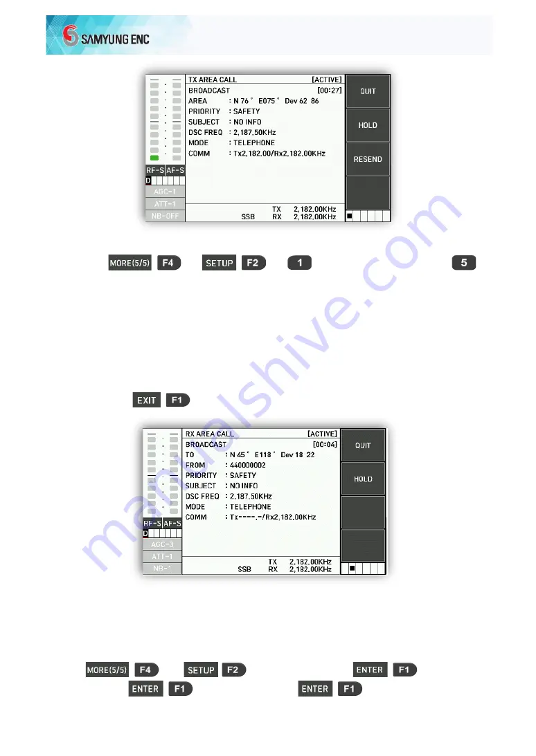
RECEPTION OF AREA CALL


1) When it is received, the alarm sounds and the settings are changed to the set 
communication frequency and mode in the call.   

2) If you press 


  the alarm stops and the alarm window disappears. 


8-6


DSC TEST 

8-6-1


DSC DOT TRASMIT 

1)


1. DSC SETUP 


9. DSC 

TEST 


1.Dot Trasmit 


Summary of Contents for SRG-150DN

Page 1: ...INSTRUCTION MANUAL MF HF SSB RADIO EQUIPMENT SRG 150DN SRG 250DN...

Page 2: ...mal operation Information to user The user s manual or instruction manual for an intentional or unintentional radiator shall caution the user that changes or modifications not expressly approved by th...

Page 3: ...3 RECEIVER SPECIFICATIONS 16 3 4 DSC DIGITAL SELECTIVE CALL W K RECEIVER 17 3 5 MF HF CONTROL 17 3 6 DIGITAL SELECTIVE CALL DSC 18 3 7 NARROW BAND DIRECT PRINTING NBDP 18 3 8 PRINTER HP 283 19 3 9 PR...

Page 4: ...LL 64 8 3 TEST CALL 67 8 4 POSITION CALL 69 8 5 AREA CALL 72 8 6 DSC TEST 74 CHAPTER 10 PRINTER 76 9 1 HP 283 PRINTER 76 9 2 JP 3750 PRINTER 78 CHAPTER11 HOW TO USE SD 250 ALARM BOX 79 10 1 DISTRESS T...

Page 5: ...ARD T 130 101 12 3 NBDP RECEIVING UNIT T 132 101 12 4 LOCAL SYNTHESIZE BOARD T 133 101 12 5 POWER CIRCUIT T 025 101 12 6 FUNCTION DIAGRAM OF REAR SIDE 102 CHAPTER 1 TROUBLE SHOOTING 103 13 1 OVERVIEW...

Page 6: ...e front panel to return to the main screen 1 1 1 INPUT SELF USER ID If you press 4 times then it will be expressed in 1 DSC SETUP 1 MMSI In you can input the desired ID number Example ID 111100000 Inp...

Page 7: ...TX RX frequency which will be used for voice communication switch to the mode Input the transmission reception TX RX frequency to use it for voice communication Press the microphone switch PTT and co...

Page 8: ...equency cannot be input with beep alarm sound Ref Press the button put on TX and if you press you can change the frequency with the dial from 10Hz to 10MHz by selecting it with the buttons Ref In CH1...

Page 9: ...stop the transmission 1 5 HOW TO USE SN 100 NBDP TERMINAL 1 5 1 CHANNEL SELECTION 1 Change CH on the screen Select the desired channel with Numeric buttons Press Enter button 2 Press F6 Select the de...

Page 10: ...ct ARQ you can be connected by ARQ MODE to the other station with the current setting channel 1 5 4 FEC MODE Press F2 and if you select FEC you can be connected by FEC MODE to the other station with t...

Page 11: ...rrow band direct printing device NBDP and used for digitized information communication suitable for automatic processing in distress safety and general situations SN 100 is used when connected to the...

Page 12: ...sible Furthermore using NBDP terminal SN 100 it is easy to create and transmit receive TELEX and view with wide front display window 2 1 4 EQUIPMENT CONFIGURATION Because SRG 150DN 250DN consists of o...

Page 13: ...R BOARD P103330 1 2 MAIN BOARD P103300 1 3 DISPLAY BOARD P103340 1 4 TX PA P103380 150W 1 5 TX FILTER P103310 150W 1 6 W K RX P103662 1 2 Automatic Antenna Tuner SAT 100 1 Installation material includ...

Page 14: ...nents NO NAME TYPE QUANTITY NOTES 1 Emergency Lamp EMG Light 1 2 External Speaker SS 10W4 1 3 POWER SUPPLY SP 1250ADC 1 4 NBDP terminal SN 100 1 Domestic including installation materials 1 Connection...

Page 15: ...L Maritime Mobile service 271EA USER CHANNEL 299EA set call and frequency directly with KEYBOARD DSC channels 2187 5 4207 5 6312 8414 5 12577 16804 5kHz FIB always receive SCAN 13 DSC channels editabl...

Page 16: ...es 5 Antenna power Power reduction 3 steps SRG 150DN J3E 50 100 150 F1B 75 100 100W SRG 250DN J3E 50 100 250 F1B 75 100 150W 6 Stability of frequency less than 10Hz SYNTHESIZER method within 0 3ppm 7...

Page 17: ...in case of 100mW DSC NBDP character error rate at a receiver input voltage 1 is less than 1 x10 2 Reception MODE FSK BAND Width 0 3 kHz 6 1 signal selectivity 3kHz FILTER for SSB details of characteri...

Page 18: ...ted from antenna terminal is less than 4000 16 Nominal input load 50 ohm unbalanced 3 4 DSC DIGITAL SELECTIVE CALL W K RECEIVER 1 Type of emission F1B 2 Frequency 2187 5 4207 5 6312 8414 5 12577 16804...

Page 19: ...3 and 541 2 2 EMISSION F1B 100BAUD 3 Modulator Output frequency 1700Hz 85Hz Output LEVEL Max 10dBm 600 ohm unbalanced balanced 4 Demodulator Input frequency 1700Hz 85Hz Input LEVEL 20dBm 5dBm 600 ohm...

Page 20: ...cy deviation within 0 5Hz 13 Compass safety distance Follow compass safety distance to prevent interference with your magnetic compass Standard Compass 2 4 m Steering Compass 1 5m 14 Demodulation inpu...

Page 21: ...olution 180DPI Printing Colums 80 Columns Buffer 128K Head life 4 billion dots Product Size 415mm W 330mm D 120mm H Weight about 7 3Kg Noise 49dB 2 Paper specifications Type number 60R L Paper size 21...

Page 22: ...ernal speaker Microphone connection jack connects the supplied microphone DISTRESS is used for DISTRESS transmission Sensitivity is used to adjust the GAIN of the amplifying stage of receiver Volume i...

Page 23: ...ut Screen Menu F1 F4 Functions You can choose DSC CALL configuration screen function DIST COMPOSE configuration screen function DROBOSE COMPOSE configuration screen function You can choose As a functi...

Page 24: ...only RX DSC Speaker Key button ON OFF Power supply status Transmission power status SCAN AMP MMSI Maritime Mobile Service Identity 2 Displays the size of reception transmission 3 W K received channel...

Page 25: ...75W SCAN 4 Scan Start Press to activate SCAN Press to stop SCAN AMP When AMP is ON Press again to turn off AMP MMSID 1 DSC SETUP Enter the MMSI ID to display the Maritime Mobile Service Identity MMSI...

Page 26: ...NB OFF Set up the Noise Blanker function Press keys to change to NB OFF NB ON Tuning Press the key on the front side to confirm ATU tuning SQL Set up the Squelch function Press key and press 3 Start S...

Page 27: ...ET VF IC 7 AUTO TUNE 8 SELF TEST 9 M 01 00 C 01 00 D 08 03 WK 01 2 Only Receive Function Only Receive Function If you press 1 DSC SETUP the following window appears MAIN MENU 1 MMSI 2 POSITION 3 TIME...

Page 28: ...front channel dial the CH is converted and you can press put it on the RX press select the frequency you want to change to and change it from 10Hz to 10MHz with the dial Ref It automatically returns w...

Page 29: ...Type is CH It is scanned to the channel When the SCAN Type is Freq it is scanned to the frequency 5 2 2 SCAN CHANNEL SET Set the setting value in case of scanning channels Choose the 2 Scan Channel Se...

Page 30: ...quency of the frequency scan 1 605 0 27 499 9KHz Speed Set the speed of the scan 1 to 15 1 fastest 15 slowest Step Set the scan interval 0 1 9 9KHz Press to return to the main screen 5 2 4 SQL TYPE SE...

Page 31: ...k on the front keyboard window the following window appears Turn the channel to choose the background color as BLACK and WHITE and set the LCD brightness as a number 5 2 6 TX POWER SET Press to choose...

Page 32: ...uipment may be damaged 3 It is possible to confirm and set the selected status of the components inside the antenna matching device 4 Press to return to the initial screen 5 2 8 ATU VERSION ATU PROGRA...

Page 33: ...SETUP screen 2 2 SSB CH Clear It is menu to delete SSB channel data and set basic channel 2 CHANNEL CLEAR If you press the following screen appears Press to delete memorized SSB channel data and set i...

Page 34: ...ange the type of front bar graph 6 TX METER SET VF IC Press to display the next screen Rotate the channel and choose the value you want to display IN V Indicates the input voltage VF Indicates the siz...

Page 35: ...01 00 MAIN CONTROLL DSP W K displays the program version 5 3 ADDITIONAL FUNCTIONS ITU CHANNEL RCV AM DSC MODE ETC 5 3 1 ITU CHANNEL ITU Channel CH401 CH2510 SSB Channel For the ITU Channel CH401 CH251...

Page 36: ...en there is no signal for 5 seconds Press to switch to another mode Ref In RCV mode TX frequency cannot be displayed 5 3 3 AM MODE If you press the following screen appears If you turn with the front...

Page 37: ...ppears If you turn with the front channel dial press put on RX and press choose frequency to which you going to change and change the frequency from 10Hz to 10MHz with the dial Ref CH1 to CH32 have no...

Page 38: ...e divided into two major types DISTRESS message DISTRESS ALERT DISTRESS RELAY AREA DISTRESS RELAY INDIVIDUAL General messages Safety urgency routine INDIVIDUAL GROUP TEST POSITION AREA POLLING Call Ex...

Page 39: ...TINE An ordinary call 4 Communication mode COMM TELEPHONE Voice call through the daily microphone speaker TLX ARQ ARQ TELEX mode via NBDP terminal TLX FEC FEC TELEX mode via NBDP terminal 5 Communicat...

Page 40: ...39 2 Individual Rx call indicates that the data with the error has been received means that there is no information...

Page 41: ...40 6 3 2 TRANSMISSION 1 DISTRESS ALERT 2 Individual Tx call...

Page 42: ...ly Start by pressing a key There are two types of Distress Alert such as MULTI SINGLE MULTI is common Please refer to Chapter 8 1 2 to set details of SINGLE and MUTI 7 1 1 SEND A DISTRESS ALERT WITHOU...

Page 43: ...nds to 4 minutes 30 seconds for a Distress Alert automatic retransmission response 8 Press the key to temporarily stop the countdown for retransmission Is displayed by Press the key while is displayed...

Page 44: ...me after the DISTRESS transmission is changed to the last time after receiving the Distress Alert response 7 1 2 MODIFY THE INFORMATION AND SEND A DISTRESS ALERT If you have time to modify the Distres...

Page 45: ...INPUT selected press the ENTER key AUTO MANUAL NOINFO AUTO The location information is automatically input from the external GPS input terminal MANUAL Manually enter location information NOINFO Input...

Page 46: ...2 West input LAT N 12 34 5678 LON E 123 45 6780 INPUT Numeric Key Enter the numeric key until you reach the end and move on to UTC input 6 Use the numeric key to enter UTC UTC 10 40 INPUT Numeric Key...

Page 47: ...elected frequency among 2 4 6 8 12 16Mhz 2M 8M 4M 6M 12M 16M OK MULTI 2M 4M 6M 8M 12M 16M OK SINGLE 9 Press the key for 3 seconds to send a Distress Alert While pressing the key an alarm sounds and th...

Page 48: ...5 Khz 4M 4125 Khz 4177 5 Khz 6M 6215 Khz 6268 Khz 8M 8291 Khz 8376 5 Khz 12M 12290 Khz 12520 Khz 16M 16420 Khz 16695 Khz 7 2 RECEPTION OF DISTRESS ALERT DISATER WARNING When a Distress Alert is receiv...

Page 49: ...e the alarm window 2 If there is no response call from the coast station while receiving a Distress Alert more than two times contact the vessel which received disaster with radio 3 Press if OK is sel...

Page 50: ...case of not receiving Distress Alert response call from the coast station for 5 minutes 2 In case of not receiving Distress Relay from another vessel 3 In case of not receiving disaster communication...

Page 51: ...utomatically 5 DSC FREQ is selected as default to 8414 5 KHz in the case of MUTI FREQ DISTRESS ALERT In the case of DISTRESS ALERT received from one frequency the frequency which received a call is se...

Page 52: ...an input the MMSI of the ship in disaster If you do not know you do not have to input it 5 If you select NATURE you can input the attribute of emergency of the ship in disaster If you do not know you...

Page 53: ...The Distress Relay shall not be transmitted unless instructed by the coast station 1 If you press on the main screen DROBOSE COMPOSE screen will be configured 2 Push the button Enter in the Format fie...

Page 54: ...7 4 DISTRESS CANCEL SENDING A CANCEL MESSAGE According the procedure below you can cancel a Distress Alert while sending a Distress Alert message and waiting for a response 1 If you press the followi...

Page 55: ...message At this time press and you will send a Distress Cancel call to the relevant band at the DSC frequency and a window will appear with instructions according to the corresponding communication m...

Page 56: ...sh the button and the Distress Cancel procedure will end 7 5 AN EXAMPLE OF PROCESSING MULTIPLE DISASTER MESSAGES 7 5 1 DISASTER MESSAGE SCENARIO No Time Type DSC FREQ Note 1 00 00 DISTRESS 4207 5Khz D...

Page 57: ...125 00Khz 7 5 3 RECEIVING THE SECOND MESSAGE Message DISTRESS ACK Received DSC frequency 4207 5Khz 1 DISTRESS ALARM sound 2 The alarm is completed only by manual operation 3 The communication frequenc...

Page 58: ...e the communication frequency of 12290KHz 5 Here is the following message 7 5 5 RECEIVING THE FOURTH MESSAGE Message DISTRESS ACK Received DSC frequency 12577Khz 1 DISTRESS ALARM sound 2 The alarm is...

Page 59: ...58 5 Input to select from 6 frequency bands...

Page 60: ...l type 3 If you select from the TO article the screen to select DIRECT INPUT ADDRESS BOOK appears DIRECT INPUT Input the MMSI by directly entering the numeric key ADDRESS BOOK It is a method to input...

Page 61: ...4208 5 Rx4220 0 LOC2 Tx4209 0 Rx4220 5 INT Tx6312 5 Rx6331 0 LOC1 Tx6313 0 Rx6331 5 LOC2 Tx6313 5 Rx6332 0 8MHz 12MHz INT Tx8415 0 5 Rx8436 5 LOC1 Tx8415 5 Rx8437 0 LOC2 Tx8416 0 Rx8437 5 INT Tx12577...

Page 62: ...X ARQ TELEPHONE TLX FEC TLX ARQ 7 Select COMM communication and communication frequency to input used communication frequency only input of the same band as the DSC calling frequency is possible If yo...

Page 63: ...hanged according to the type of response and it can communicate with the other station 10 There are 3 types of response ACCEPT REFUSE CHANGE ACCEPT The response agreed to communication frequency at wh...

Page 64: ...not change to the corresponding frequency 8 1 2 RECEIVING AN INDIVIDUAL CALL 1 Set up REFUSE auto responder If the communication frequency or mode of the received call is not available you can set th...

Page 65: ...as sent an Individual Call for the following reasons by pressing its REASON selection window appears where you can select the response CHANGE Response with changing the communication frequency at the...

Page 66: ...MMSI by selecting from entered names 4 DSC article is the same as the PRIORITY ROUTINE input of INDIVIDUAL 5 You can select TELEPHONE TELEX in MODE article TELEPHONE TELEX 6 If COMM communication and...

Page 67: ...eive and wait for DSC reception GROUP call is called at the frequency which W K cannot receive 2 3 ADDRESS BOOK In case of receiving GROUP call it is received by GROUP MMSI registered in 2 GROUP 3 Whe...

Page 68: ...s 8 3 TEST CALL 8 3 1 TEST CALL RECEIVING 1 Press on the main screen and the DSC CALL screen is configured 2 If you press TYPE selection window is displayed if you select TEST it shifts into TEST call...

Page 69: ...ct SHIP STATION COAST STATION individually 4 If you select the DSC item enter the DSC frequency you want to call 2187 5Khz 4207 5Khz 6312 0Khz 8414 5Khz 12577 0Khz 16804 5Khz 5 Press to send TEST call...

Page 70: ...n turn it ON in 1 AUTO ACK TEST ON ON When AUTO ACK is ON when receiving TEST call alarm doesn t sound and alarm window doesn t appear on the screen Also the TEST DSC receiving screen is not displayed...

Page 71: ...configuration screen INDIVIDUAL GROUP TEST POSITION AREA 3 If you select the TO article the screen to select DIRECT INPUT ADDRESS BOOK appears DIRECT INPUT Input the MMSI by directly entering the num...

Page 72: ...eceiving a request call for location information 1 DSC SETUP 4 AUTO ACK SET You can turn it ON in 3 AUTO ACK POSITION ON When AUTO ACK is ON when receiving a call request for location information a ca...

Page 73: ...main screen DSC CALL is configured 2 If you press TYPE selection window is displayed If you select AREA it changes to AREA call configuration screen INDIVIDUAL GROUP TEST POSITION AREA 3 If you selec...

Page 74: ...8414 5Khz 12577 0Khz 16804 5Khz 5 You can select TELEPHONE TELEX in the article MODE TELEPHONE TELEX 6 If you select COMM you can input the communication frequency to be used and only the input of th...

Page 75: ...f select the SUBJECT in the AREA configure screen 8 5 2 RECEPTION OF AREA CALL 1 When it is received the alarm sounds and the settings are changed to the set communication frequency and mode in the ca...

Page 76: ...Mark signal at 4207 50Khz 8 6 3 SPACE TRASMIT 1 1 DSC SETUP 9 DSC TEST 3 Space Trasmit 2 Send the Space signal at 4207 50Khz 8 6 4 LOOP TEST 1 DSC SETUP 9 DSC TEST 4 DSCLOOP TEST The following screen...

Page 77: ...solvent Precautions during operation Empty parameters should be avoided when the PRINTER paper is not inserted During printing do not turn off the power switch but switch the head of PRINTER to HOME P...

Page 78: ...INTER Cut the end of the paper at right angles If paper is inserted in a wrinkled state paper clogging may occur How to use PRINTER paper Set the POWER switch on the PRINTER to OFF Open the cover and...

Page 79: ...nsert the ROLL paper support cap into the socket on the back of the printer Move the handle lever toward the front side so that the column indicator comes off the platen Position the paper release lev...

Page 80: ...rted to work and location of disaster time ship s ID are sent to DSC 6 CH in order If there is no answer it does sending till getting an answer through CH1 to CH 6 2 In order to stop the transmitting...

Page 81: ...ransmit receive frequency indication VOLUME RF GAIN CLARIFY ATT TX POWER AGC and Function key Speaker Sounds when receiving data or receiving alarm Transmitting LED LED turns red when transmitting Rec...

Page 82: ...ow keys and adjust it to an appropriate value 0 to 100 steps This function adjusts intelligibility when receiving It can be increased or decreased by using up down buttons to adjust receive listening...

Page 83: ...splay Main Menu 0 ARQ Communicate Automatic Repeat Request mode 1 FEC Communicate Forward Error Correction mode 2 Station Edit Register the frequency of the other station 3 Station Print Print out the...

Page 84: ...05MHz 27 499MHz 11 3 2 SETTING RX FREQUENCY Press F8 button Input the frequency with Number button Ref While inputting frequency if press curser will move Press Enter button Ref Available RX Frequency...

Page 85: ...BY CALLING CHANNEL Press F6 in Keyboard Input the channel with Number button Press Enter button 11 4 ARQ MODE 11 4 1 CONNECTING WITH THE OTHER STATION BYARQMODE Connecting by present adjusting channel...

Page 86: ...Press F10 on the keyboard Main Menu screen display Move the cursor with button to 0 ARQ press Enter and the following screen will appear Revert the other station you want to communicate using button...

Page 87: ...t top of the screen 11 4 3 COMMUNICATION IN ARQ MODE Perform 14 4 1 or 14 4 2 and operate as below order As long as you can connect with the other station in ARQ mode above screen is displayed You can...

Page 88: ...ntence no Written in Macro Command Refer to 14 4 5 Macro Command RX F7 7Over Convert the direction of transmitting the message F8 8Stop Stop communication F9 9VOL Volume can be reduced F10 0VOL Volume...

Page 89: ...ard and LINK MENU screen shows Move the cursor to 2 FEC with button Press Enter and the following screen shows Revert the other station you want to communicate using button press Enter button the foll...

Page 90: ...F8 and it will be back to Telex initial screen If connected with other station cursor blinks on the left top of the screen 11 5 2 CONNECTING WITH THE OTHER STATION BY COLLECTIVE FEC MODE Press F10 bu...

Page 91: ...age via KEYBOARD then press Enter allow transmitting Ref if do not press Enter then transmit cannot be made Keys can be used by FEC mode Characters ABCDEFGHIJKLMNOPQRSTUVWXYZ1234567890 abcdefghijklmno...

Page 92: ...be saved In order to open the file press F10 5 Editor mode choose Enter F1 1 Lord RECV 01 choose file among RECV 20 press Enter 11 5 5 RECEIVING FILE Carry out above 14 5 1 or 14 5 2 then follow belo...

Page 93: ...N EDIT AND FREQUENCY REGISTRATION Maine menu will be displayed by press F10 as below Move cursor by up down arrow key then choose 2 Station Edit below screen will be displayed by pressing Enter Choose...

Page 94: ...ess Enter Input receive frequency saved by pressing Enter Return to initial screen by pressing ESC key 11 7 STATION PRINT OPPOSITE SIDE COUNTRY AND FREQUENCY PRINT OUTPUT Below Main Menu will be displ...

Page 95: ...Menu will be displayed by pressing F10 Move cursor by up down arrow to 4 Macro Command below screen will be displayed by pressing Enter Choose Command by arrow button Enter input Command by keyboard...

Page 96: ...mber screen return and save Edit message screen by pressing Enter open and see saved sentence FEC received NAVTEX data by pressing F1 Ref user can save file from Slot 01 to Slot 20 from RECV 01 to REC...

Page 97: ...d at installation stage setting 1 ARQ FEC 9 digit ID After choose 1 ARQ FEC 9 digit ID Enter input number key Enter return and saved to Main Menu by pressing ESC Ref user cannot change saved at instal...

Page 98: ...Station Selection Enter NAVTEX Station Selection will appear Choose initial character of the broadcast station by left right arrow button and Enter save and return to System setting Menu by pressing E...

Page 99: ...reset with button Enter button 0 Language Set Set up Language Korean Russian English 1 Printer Type Set up Printer type JP 3750 HP 083 2 Printer Port Local Main unit printer Remote SN 100 printer can...

Page 100: ...with button Press Enter and each function operates 1 Mark Transmission 1 7 kHz 85 Hz signal is transmitted for 40 seconds 2 Space Transmission 1 7 kHz 85 Hz signal is transmitted for 40 seconds 3 Dot...

Page 101: ...ew Perform NBDP RX TX Test and check the test result is ok 11 12 LCD OFF 1 Operation on MENU Press F10 button on the keyboard and Main Menu screen shows Move the cursor to 8 LCD Off F12 with button pr...

Page 102: ...mplifier MIXER ATT AGC B K control circuit After the signals received through MF HF Antenna amplify with wide amplifier it is divided into two parts through SPLITTER SP1 Among them one of RF signal go...

Page 103: ...ANT OUT Connect which send W K signal Received from RX ant in to main unit KEY BOARD Connect between keyboard and SN 100 Supply 5V Data CLK etc GND Receiver System ground FUSE 5A FUSE Printer 24V FUSE...

Page 104: ...aintenance adjustment of this equipment have to control from correcting test center by rated testers must have testers for maintenance adjustment daily as follow 1 Multi tester for check that don t ne...

Page 105: ...is 21 6 26 4V it s correct Have to maintenance if over or less the badness of power supply equipment POWER SUPPLY or BATTERY d Change same goods if check power circuit P1003300 PCB SRG 3150DN is defec...

Page 106: ...d If 5V is not supplied CPU BOARD is not operated 2 SCREEN DISPLAY Screen is not turned on Check if power is correctly supplied to LCD Screen is waved or there is white line on the screen If the condi...

Page 107: ...unit please get access to dummy load 2 In case of separating PCB please pay attention to static electronic 3 In case of modulating please use the exclusive tools for modulation 4 In case of checking o...

Reviews: