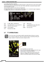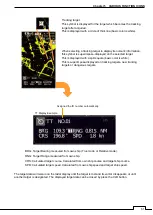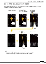
74
Chapter 5 VARIOUS FUNCTION ICONS
5.14 MOTION MODE
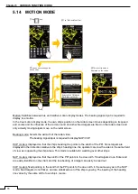
Motion: Switches between true and relative motion display modes. The bearing signal input is required to
display true motion.
In the true motion display mode, t
he own ship’s position on the radar screen moves depending on its speed
and course and the influence of the current. Land and other fixed targets are fixed on the radar screen and
only actually moving targets move on the radar screen.
Bearing mode: Selects the azimuth of the radar video.
The bearing signal input is required to display NUP/CUP.
HUP mode is
displayed so that the ship’s heading line points to the zenith of the PPI. Since targets are
displayed in their direction relative to the ship’s heading line, the operator can view the video in the same field
of view as in operating the ship at sea. This mode is suitable for watching over other ships.
NUP mode is displayed so that the zenith of the PPI points to the due north. Fixed targets do no flicker and
are easily identified on the chart, and the true bearing of a target can easily be read out.
CUP mode is fixed pointing to the zenith of the PPI points to the due north. In the same way as in the NUP
mode, fixed targets do not flicker, and are stabilized even if the ship is yawing. The bearing of the heading
line varies by the same shift of own ship’s course.
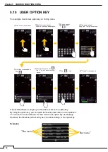
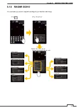
①Tap icon.
②Tap “Motion Mode” bar .
③Tap any one to change the
motion mode.
Selected the RM Motion
Selected the TM Motion
(HUP does not work)
④The selected mode is
displayed on the screen.
Summary of Contents for SMR-715 series
Page 1: ...MARINE RADAR EQUIPMENT INSTRUCTION MANUAL...
Page 2: ......
Page 15: ...xiii EQUIPMENT APPEARANCE NKE 1066 SCANNER UNIT NKE 2044 SCANNER UNIT...
Page 29: ...Chapter 1 INSTALLATION 3 1 2 3 DIMENSIONAL DRAWING OF DISPLAY MOUNTING...
Page 30: ...Chapter 1 INSTALLATION 4...
Page 32: ...Chapter 1 INSTALLATION 6 DESKTOP MOUNTING TEMPLATE Note Please note the paper size 182 257...
Page 34: ...Chapter 1 INSTALLATION 8 FLUSH MOUNTING TEMPLATE Note Please note the paper size 182 257...
Page 43: ...Chapter 1 INSTALLATION 17 NKE 2044 2FT SCANNER Fig 1 3 6 3 Fig 1 3 6 4...
Page 47: ...Chapter 1 INSTALLATION 21 Fig 1 4 1 3...
Page 51: ...Chapter 1 INSTALLATION 25 Fig 1 4 2 3...
Page 157: ...131 Chapter 10 AFTER SALE SERVICE 10 4 RADAR FAILURE CHECK LIST SMR...
Page 159: ...133 Chapter 12 SPECIFICATIONS Chapter 12 SPECIFICATIONS...
Page 160: ...134 Chapter 12 SPECIFICATIONS 12 1 SCANNER DIMENSION 12 1 1 NKE 1066 4 40 RUBBER PLATE...
Page 161: ...135 Chapter 12 SPECIFICATIONS 12 1 2 NKE 2044...
Page 162: ...136 Chapter 12 SPECIFICATIONS 12 2 DISPLAY DIMENSION 12 2 1 SMR 715 720...
Page 163: ...137 Chapter 12 SPECIFICATIONS...
Page 172: ...APPENDIX A 1 APPENDIX NKE 1066 1 5FT SCANNER INTERCONNECTION DIAGRAM FIG A1...
Page 173: ...APPENDIX A 2 NKE 2044 2FT SCANNER INTERCONNECTION DIAGRAM FIG A2...
Page 174: ...APPENDIX A 3 SMR 715 720 DISPLAY UNIT INTER CONNECTION DIAGRAM FIG A3...
Page 175: ...APPENDIX A 4 SMR 715 720 PRIMARY POWER SUPPLY DIAGRAM FIG A4...
Page 176: ...APPENDIX A 5 SMR 715 720 INTERCONNECTION DIAGRAM FIG A5...
Page 177: ...APPENDIX A 6 MEMO...
Page 187: ...APPENDIX A 16 DECLARATION OF CONFORMITY...
Page 188: ...APPENDIX A 17...
Page 189: ...APPENDIX...
Page 191: ...Chapter 3 ADJUST THE RADAR ECHO A 2...
Page 192: ...Chapter 3 ADJUST THE RADAR ECHO...

