


English
_23
●
in
St
aLL
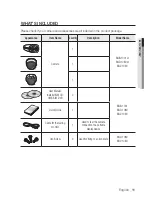
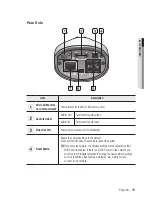
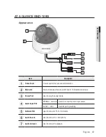
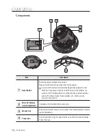
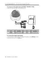
ation & connection
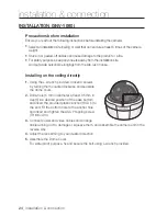
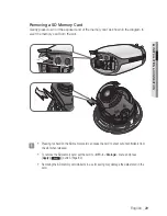
2.
Push the release lock out while turning the main unit in
the <
unLocK
> direction to remove the bracket.
If this doesn’t work, use the hole on the bottom of the
bracket to turn the bracket in the <
LocK
> direction.
3.
Use the provided screws (x3) to fix the bracket to a desired position (ceiling or wall).
`
Ensure that the <
FRONT
> label on the bracket faces the direction for camera monitoring.
4.
Arrange the cables through the bracket to
the ceiling or wall.
If you intend to drill a hole in the installation
site for the wiring purpose, remove the wiring
cover by force to reveal a hole. Arrange the
cables through the hole. If you intend to
arrange the cables without drilling a hole, use
the empty area opposite to the <
front
>
label side for the wiring purpose.
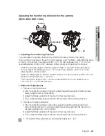
5.
Mount the main unit onto the bracket.
Align the marking hole of the main unit with
the <
front
> label of the bracket, and turn
the unit in the <
LocK
> direction.
6.
Adjust the lens in a desired direction.
For adjusting the lens direction, refer to “
adjusting the monitoring direction for the
camera
”. (page 25)
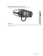
7.
Fix the cover to the main unit.
Fit the protruding part inside the cover into the corresponding hole of the main unit,
and turn the cover to fix it.
Wiring Cover
UNLOCK
Summary of Contents for SNB-1001
Page 1: ...NETWORK CAMERA User Manual SNB 1001 SND 1080 SNV 1080 ...
Page 102: ...appendix Product Overview Unit mm inch SNB 1001 74 3 2 93 114 4 4 50 54 5 2 15 102_ appendix ...
Page 103: ...SND 1080 Ø115 8 4 56 115 8 4 56 42 4 1 67 92 7 3 65 English _103 appendix ...
Page 104: ...appendix SNV 1080 Ø137 0 5 39 Ø100 0 3 94 105 9 4 17 104_ appendix ...