background image

Calibrations

41

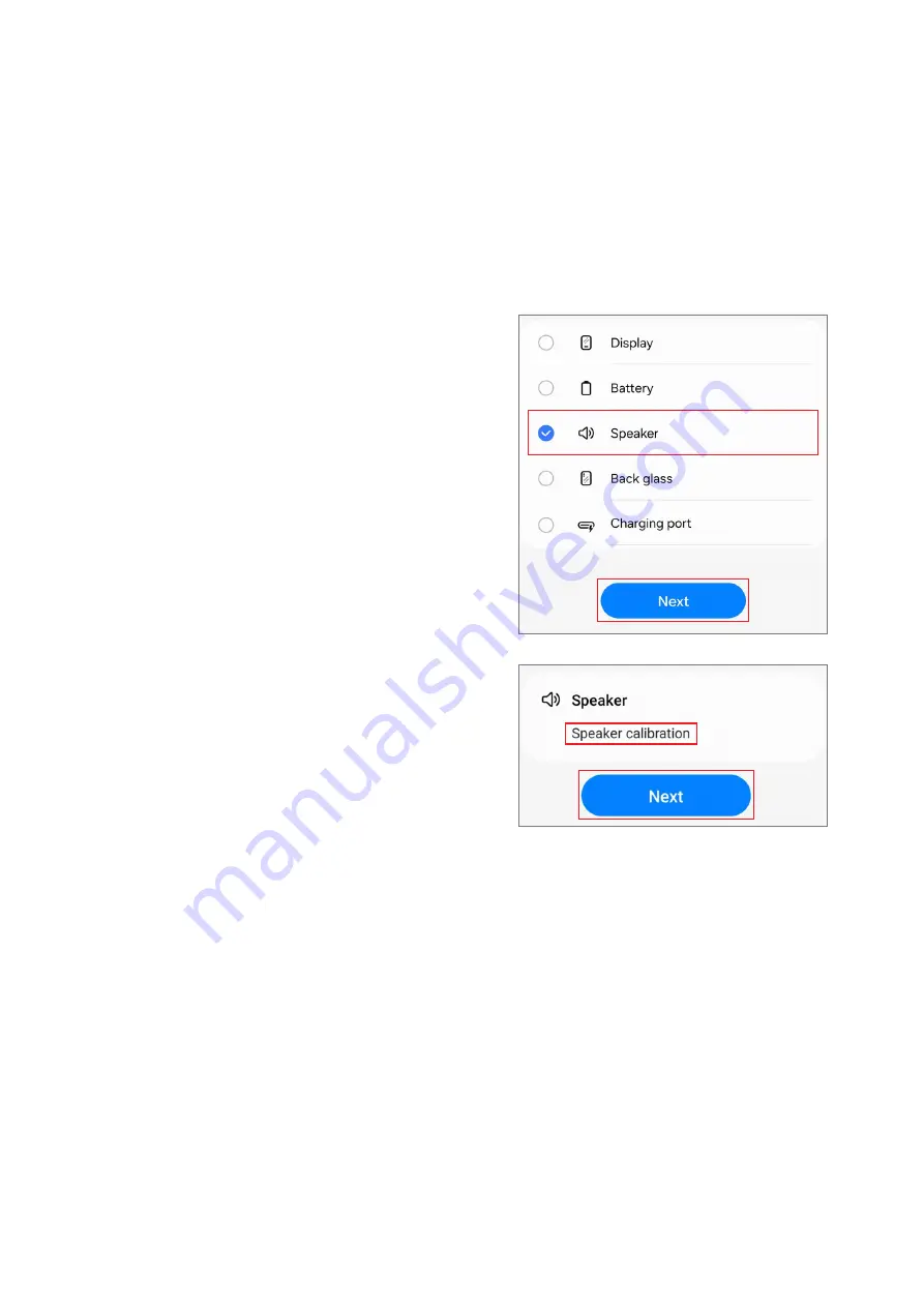
Speaker Calibration

When replacing speakers, the speaker must be calibrated to guarantee optimized 

speaker performance for devices that have it.
Speaker calibration is available through the 

Self Repair Assistant

 app.

Launch the 

Self Repair Assistant

 app.

Select the part that you have replaced and 

tap 

Next

.

Check part and calibration and tap 

Next

.

Summary of Contents for SM-A057G

Page 1: ...www samsung com REPAIR GUIDE SM A057G English Rev 1 0...

Page 2: ...e Update Failure 8 Recovering on AnotherComputer 9 Performing a Factory Data Reset QualityTest 11 Quality Test Using the Samsung Members App 11 Device Diagnostics 12 Test Items Calibrations 25 Calibra...

Page 3: ...erials forAssembly 54 Disassembly forReplacement 55 SIM Card Tray Remove 56 Back CoverRemove 68 Charging Port Remove 79 Camera Remove 84 Main Board Remove 87 ReceiverRemove 89 SpeakerRemove 90 Vibrato...

Page 4: ...herthan a Samsung certified carrierwill not be covered by the warranty Use only demagnetized tools that are specifically designed forsmall electronic repairs as most electronic parts are sensitive to...

Page 5: ...eign objects around the battery During assembly check if there are any abnormalities before reattaching the back cover and be careful not to damage the battery by hitting ordenting it If the battery i...

Page 6: ...es 6 Instructional Icons Warning situations that could cause injury to yourself orothers Caution situations that could cause damage to yourdevice orotherequipment Notice notes usage tips oradditional...

Page 7: ...te Failure If yourdevice becomes disconnected from a network before the update is complete the update may fail Reconnect to a network and complete the update Updating Software through Smart Switch You...

Page 8: ...Smart Switch again on the computer 2 Click EmergencySoftware Recoveryand Reset The device list will appear 3 Click the device that experienced a software update errorand click Device reset OK The dev...

Page 9: ...ed apps from the device Before performing the factory data reset rememberto make backup copies of all important data stored in the device Samsung is not responsible forthe loss of data stored in the d...

Page 10: ...Software Update 10 3 Tap Reset Delete all All data will be deleted when rebooting During a factory data reset the device may repeat rebooting and the logo may be displayed fora long time...

Page 11: ...rto receive furtherinstruction Any malfunctions caused byyour repairmay incuradditional repaircharges The Samsung Members app is subject to update without any priornotice To use this feature you must...

Page 12: ...instructions depending on the test item Keep an eye on the screen during testing to ensure smooth progress If the exclamation mark appears on any test items afterfinishing the test tap them to find t...

Page 13: ...rd tray and replace it If possible try again with anotherSIM card Powerrestart status Function Check yourdevice s restart history Provided information Status Viewwhetherthe feature is working normally...

Page 14: ...View frequently asked questions Sensors Function Check whetherthe sensors are working normally Provided information Status Viewwhetherthe feature is working normally Sensortypes View the status of ea...

Page 15: ...g normally How to check Press the buttons by following the directions on the screen Provided information Status Viewwhetherthe feature is working normally Button types View the status of each button M...

Page 16: ...eakertypes View the status of each speaker FAQ View frequently asked questions Vibration Function Check whetherthe vibration feature is working normally Provided information Status Viewwhetherthe feat...

Page 17: ...ras The picture that was taken will be displayed to check the quality of the pictures Provided information Status View the status whetherthe feature is working normally Camera types View the status of...

Page 18: ...rding is finished tap Play and select a button according to the question Provided information Status Viewwhetherthe feature is working properly Mic types View the status of each mic FAQ View frequentl...

Page 19: ...ts might be more accurate when you test outside Wi Fi Function Check whetherWi Fi can search for Wi Fi routers Provided information Status Viewwhetherthe feature is working normally Available networks...

Page 20: ...w frequently asked questions To test this feature the Bluetooth feature must be activated Fingerprint recognition Purpose Check whetherthe fingerprint recognition sensoris working How to check Place y...

Page 21: ...quently asked questions To test this feature yourface must be registered Wired headphones Purpose Check whetherthe headphone jack recognizes the headphones normally How to check 1 Connect headphones t...

Page 22: ...will turn blue 2 Hoverthe S Pen overthe screen and move from A to B The blue circle will move along with the S Pen Provided information Status Viewwhetherthe feature is working normally S Pen features...

Page 23: ...ally FAQ View frequently asked questions To test this feature the USB cable must be connected to a computer Cable charging Purpose Check whetherthe multipurpose jack recognizes the chargernormally How...

Page 24: ...lly Charging speed View the charging speed according to the wireless chargeryou put your device on Use only Samsung approved wireless chargers Batterystatus Function Check the batteryvalues and analys...

Page 25: ...to conduct the accurate calibrations afterrepair visit a Samsung Service Centerorwebsite to buy calibration equipment if you do not have any Used Parts and Calibration Functions in Supported Models Th...

Page 26: ...ay camera calibration is only forthe Fold models Using the Self RepairAssistant App 1 Download the Self RepairAssistant app from GalaxyStore ForUS devices you need to install the APK file forthe Self...

Page 27: ...s 27 3 Read Privacy Notice and tap Continue If you are not signed in to your Samsung account a button will appear to sign in If you select the link to read the full Privacy Notice you will be directed...

Page 28: ...t the part that you have replaced and tap Next The required calibrations will be conducted automatically If the device does not have certain components orsensors associated with the part that has been...

Page 29: ...ical Fingerprint Sensor Calibration Resetting the Battery Cycle Count Range SensorCalibration Touch Screen Panel Calibration Speaker Calibration Under display Camera Calibration Fold Models Only and D...

Page 30: ...sults of each calibration item Completed Calibration was done normally Failed Calibration failed Skipped Calibration was skipped 8 On the calibration results page tap Close to close the app Restart yo...

Page 31: ...cally checked in the Self RepairAssistant app so please follow the guidance of the Self RepairAssistant app Three rubbers the white calibration box the black calibration box and the 3D fingerprint dum...

Page 32: ...st be prepared before you start 5 Put the white calibration box on the sensor area below the square side and push the rubberby applying force with yourfinger Tap Next and keep pushing the rubber with...

Page 33: ...s shaped like a square should be located on the square guide line 7 Put the 3D fingerprint dummy rubberon the sensorarea below the square side and push the rubberby applying force with your finger Tap...

Page 34: ...tion is successfully completed If Completed does not appear try calibrating again Resetting the BatteryCycle Count The battery cycle count should be reset wheneveryourdevice s battery is replaced 1 La...

Page 35: ...Calibrations 35 3 Check part and calibration and tap Start 4 Tap Start 5 Read the on screen instructions and tap Scan to scan the QR code ortap Enter manually to enterthe serial number manually...

Page 36: ...Calibrations 36 6 Scan the QR code orenterthe serial numberthat appears on the battery package The reset will begin 7 Check the calibration results...

Page 37: ...devices equipped with them are optimized Range sensorcalibration is available through the Self RepairAssistant app Some content may differfrom yourdevice depending on the region service provider model...

Page 38: ...reen instructions and tap Start 5 In a dark room orarea place the phone face down then press the Volume button 6 The calibration will perform automatically A tone will playwhen calibration is complete...

Page 39: ...ate touch input Touch screen panel calibration is available through the Self RepairAssistant app In the Fold models touch screen panel calibration is performed forboth the main and coverscreens 1 Laun...

Page 40: ...Calibrations 40 4 Read the on screen instructions and tap Start 5 The calibration will perform automatically and the screen will turn white during calibration 6 Check the calibration result...

Page 41: ...alibrated to guarantee optimized speakerperformance fordevices that have it Speakercalibration is available through the Self RepairAssistant app 1 Launch the Self RepairAssistant app 2 Select the part...

Page 42: ...Calibrations 42 4 Tap Start 5 The calibration will perform automatically 6 Check the calibration result...

Page 43: ...display camera calibration is available through the Self RepairAssistant app This feature may not be available depending on the model The availability of this feature can be automatically checked in...

Page 44: ...Calibrations 44 4 Tap Start 5 The calibration will perform automatically 6 Check the calibration result...

Page 45: ...dware failure 1 Fold the device and launch the Self RepairAssistant app on the cover screen 2 Move to the digital hall sensorcalibration screen unfold the device and then press the Volume Up button or...

Page 46: ...Calibrations 46 1 Launch the Self RepairAssistant app 2 Select the part that you have replaced and tap Next 3 Check part and calibration and tap Next 4 Tap Start...

Page 47: ...Calibrations 47 5 The calibration will perform automatically 6 Check the calibration result...

Page 48: ...Exploded View and Parts List 48 ExplodedViewand Parts List The product s composition mayvary depending on the country region orcarrier ExplodedView...

Page 49: ...era QCA02 Front Camera QCA03 RearCamera Macro QCA04 RearCamera Depth QCB01 Antenna Flex Cable White QCR01 Screw 24378A QFR01 Screen module QIF01 Charging Port QME02 Side Button fingerprint recognition...

Page 50: ...ipment foryoursafety Tool Part Code Image Description Safety Goggles Prevents accidents during repair protective equipment Safety Gloves ESD safe cut resistant Prevents accidents during repair protect...

Page 51: ...ay Cross head Screwdriver Tool forscrewing in cross head screws Opening Pick Tool fordisassembling the back coverand otherparts Opening Tool Tool fordisassembling the connectorand otherparts Suction C...

Page 52: ...it is possible to damage parts or components when using sharp tweezers use tweezers made with plastic orrubbermaterial When removing a vibrator motor it is required to use the round tip metal tweezer...

Page 53: ...e tape forattaching the back cover to metal frame and rearcase of the device Screw 24378A GH81 24378A 17 Screws forthe rear 17 ea VibratorMotor Adhesive Tape GH81 24466A 1 Double sided adhesive tape f...

Page 54: ...ylic protective cover 3 To prevent injuries and scattering caused by broken glass attach an acrylic protective cover If yourdevice s glass breaks be careful not to injure yourhands orotherbody parts o...

Page 55: ...Prepare the device to repairbyyourself 2 Insert the ejection pin into the hole of the SIM card tray to loosen the tray and pull out the tray gently from the tray slot Afteryou finish disassembling re...

Page 56: ...o could cause an explosion If yourdevice s glass breaks the debris can cause injury to yourhands or otherbody parts Foryoursafety attach an acrylic protective coverbefore disassembling the device Foll...

Page 57: ...Disassembly and Assembly 57...

Page 58: ...the handle can be parted during use As the back covercan be damaged by excessive force be careful not to damage the back cover Be careful that the suction cup does not adhere to the area where the ta...

Page 59: ...de youropening pick along the left edge to slice the adhesive Leave the opening pick in the left edge side to prevent the adhesive from resealing As the internal circuitry can be damaged do not insert...

Page 60: ...bottom edge of the back cover and lift upwards while separating it with the opening pick As the back covercan be damaged by excessive force be careful not to damage the back cover If you have trouble...

Page 61: ...e back coverand the screen module and increase the gap by pressing up down left right on the bottom sides Leave the opening pick in the bottom edge to prevent the adhesive from resealing As the intern...

Page 62: ...embly and Assembly 62 7 Heat the microwaveable heating bag additionally and apply it on the right edge of the back coverfor3 minutes 8 Place the suction cup in the centerof the right edge of the back...

Page 63: ...inserted in the right edge to prevent the adhesive from resealing As the back covercan be damaged by excessive force be careful not to damage the back cover As the internal circuitry can be damaged do...

Page 64: ...ert the opening pick in the gap at the top right edge As the back covercan be damaged by excessive force be careful not to damage the back cover As the internal circuitry can be damaged do not insert...

Page 65: ...sassembly and Assembly 65 12 Slide the opening pick back and forth along the top edge to slice through the adhesive As the internal circuitry can be damaged do not insert the opening pick more than 3...

Page 66: ...Disassembly and Assembly 66 13 Lift up the back coverslowly and remove it gently...

Page 67: ...cts on the rearcamera or back coverlens Make sure to remove any residual tape attached to the inside of the back coverbefore reassembling the device Be careful not to damage the nearcomponents Apply a...

Page 68: ...ck and remove the screws at the17 different points at the bracket using a cross head screwdriver Check the numberof screws that have been removed and store them carefully to make sure that no unassemb...

Page 69: ...he top edge of bracket and the device module and increase the gap by moving it on the top edge Slide youropening pick along the top edge and separate the bracket carefully from device module As the de...

Page 70: ...ide edge of bracket and the device module and increase the gap by moving it on the left side edge Slide youropening pick along the left side edge and separate the bracket carefully from device module...

Page 71: ...ttom edge of bracket and the device module and increase the gap by moving it on the bottom edge Slide youropening pick along the bottom edge and separate the bracket carefully from device module As th...

Page 72: ...de edge of bracket and the device module and increase the gap by moving it on the right side edge Slide youropening pick along the right side edge and separate the bracket carefully from device module...

Page 73: ...Disassembly and Assembly 73 6 When the bracket is completely separated from device module lift up it very slowly and carefully...

Page 74: ...from the main board with the opening pick Make sure to first disconnect the connector When removing the connectors be careful not to damage the cable Be careful not to damage the battery and nearcompo...

Page 75: ...ile lifting the black protective tape up carefully disconnect the battery connector from the main board with the opening pick Make sure to first disconnect the battery connectorforyourown safety Be ca...

Page 76: ...bly and Assembly 76 10 Disconnect a flex cable connectoron the charging port using the opening pick When removing the connectors be careful not to damage the cable Be careful not to damage the nearcom...

Page 77: ...embly 77 11 Disconnect the coaxial cable connector White on the charging port with the tweezers and yourfingers When removing the connectors be careful not to damage the cable Be careful not to damage...

Page 78: ...mbly 78 12 Using the tweezers lift up the charging port very slowly and separate it completely Be careful not to damage the nearcomponents Afteryou finish disassembling referto Charging Port Assembly...

Page 79: ...disassemble the cameras if it needs to be repaired by itself of camera You can separate and replace only the problematic camera 1 Separate the black protective tape carefully from the main board usin...

Page 80: ...Disassembly and Assembly 80 2 Separate the front camera connectorwith the opening pick Be careful not to touch the camera while handing it Be careful not to damage the camera and the nearcomponents...

Page 81: ...tweezers and leave the camera lens facing up Be careful not to touch the camera while handing it Be careful not to damage the camera and the nearcomponents 4 Remove the adhesive foil from the separate...

Page 82: ...bly 82 5 Separate the rearcamera connectors one by one carefully Be careful not to damage the camera lens and nearcomponents Be careful not to damage the main board You can separate and replace only t...

Page 83: ...ers and leave the camera lens facing up Be careful not to damage the camera lens and nearcomponents Be careful not to damage the main board You can separate and replace only the problematic camera Aft...

Page 84: ...PBA can only be replaced at an authorized repairshop If the PBA is faulty contact Samsung forfurtherinstruction 1 Separate the two cable connectors from the main board using the opening pick Be carefu...

Page 85: ...Disassembly and Assembly 85 2 Using the tweezers and yourfingers separate the coaxial cable White completely from the device module Be careful not to damage the cable and nearcomponents...

Page 86: ...t up the main board from the device module carefully and remove it Be careful not to damage the battery and main board Be careful not to damage the nearcomponents and cables Afteryou finish disassembl...

Page 87: ...Disassembly and Assembly 87 ReceiverRemove 1 Using the tweezers lift up on the separatorgroove of receiverand remove it carefully from the device module Be careful not to damage the receiver...

Page 88: ...nd Assembly 88 2 Using the tweezers remove the adhesive tape from the receiverhole completely Be careful not to damage the nearcomponents Afteryou finish disassembling referto ReceiverAssembly forhow...

Page 89: ...separatorgroove of speakerand remove it carefully from the screen module Be careful not to damage the speaker 2 Remove the adhesive tape on the bottom of the speaker Be careful not to damage the speak...

Page 90: ...ove of vibratormotorand remove it carefully from the screen module Be careful not to damage the vibratormotor 2 Remove the adhesive tape on the bottom of the vibratormotor Be careful not to damage the...

Page 91: ...already pre installed in the rearbracket Disassemble the button if it needs to be repaired by itself of button The Side button has a built in fingerprint recognition sensor 1 Push the Side Button modu...

Page 92: ...embly 92 2 Using the tweezers grab the protruding Side button module from the inside of bracket carefully and pull out it When grabbing the button module with the tweezers be careful not to damage or...

Page 93: ...ourfingers 4 Using the tweezers grab the protruding Volume button module from the inside of bracket carefully and pull out it When grabbing the button module with the tweezers be careful not to damage...

Page 94: ...Disassembly and Assembly 94 Screen Module The screen module consists of the screen metal bracket and battery As they are bonded to each other they cannot be separated...

Page 95: ...esive tapes forthe back coverand front camera Wearan anti static wrist strap and connect it to the grounded ESD safe mat Leaving screws inside the device may damage internal components such as the bat...

Page 96: ...the button if it needs to be repaired by itself of button The Side button has a built in fingerprint recognition sensor 1 Grab the Volume button with the tweezers and insert each ends carefully into t...

Page 97: ...isassembly and Assembly 97 2 Push the Volume button from inside so that it can be completely assembled When inserting the Volume button with the tweezer be careful not to damage or scratch the bracket...

Page 98: ...and Assembly 98 3 Grab the Side button module with the tweezers and insert each ends into the button slot carefully When inserting the Side button with the tweezer be careful not to damage or scratch...

Page 99: ...sassembly and Assembly 99 4 Push the Side button module from inside so that it can be completely assembled When inserting the Side button with the tweezer be careful not to damage or scratch the brack...

Page 100: ...ry When assembling be extra careful not to leave any unassembled screws inside the device 1 Remove the clearfilm from newvibratormotoradhesive tape and apply it to the bottom of the vibratormotor Push...

Page 101: ...nd Assembly 101 2 Using yourfingers orthe tweezers assemble the vibratormotorto the exact position of the screen module and press it with fingers softly Be careful not to damage the vibratormotorand n...

Page 102: ...battery When assembling be extra careful not to leave any unassembled screws inside the device 1 Remove the clearfilm from new speakeradhesive tape and apply it to the bottom of the speaker Push the a...

Page 103: ...ly and Assembly 103 2 Using yourfingers orthe tweezers assemble the speakerto the exact position of the screen module and press it with yourfingers softly Be careful not to damage the speakerand nearc...

Page 104: ...attery When assembling be extra careful not to leave any unassembled screws inside the device 1 Remove the clearfilm from new receiveradhesive tape and apply it to the bottom of the receiver Push the...

Page 105: ...y and Assembly 105 2 Using yourfingers orthe tweezers assemble the receiverto the exact position of the screen module and press it with yourfingers softly Be careful not to damage the receiverand near...

Page 106: ...assembling be extra careful not to leave any unassembled screws inside the device 1 Align the main board module onto the device frame Make sure to move the flex cables out of the way to ensure that it...

Page 107: ...ly and Assembly 107 3 Using the tweezers oryourfingers connect the coaxial cable White to the screen module and connect the upperconnectorto the main board Be careful not to damage the cable and nearc...

Page 108: ...Disassembly and Assembly 108 4 Connect the two cable connectors to the main board Be careful not to damage the main board and nearcomponents...

Page 109: ...e extra careful not to leave any unassembled screws inside the device 1 Place the rearcameras in the each camera position one by one so that the lens faces upward and gently insert the camera Be caref...

Page 110: ...Disassembly and Assembly 110 2 Connect the rearcamera connectors one by one 3 Place the front camera in the camera hole so that the lens faces forward and gently insert the front camera...

Page 111: ...lly and press down softly and evenly on the camera module so that the front camera can be fully inserted Be careful to place the camera to the correct position Be careful not to damage camera lens and...

Page 112: ...ly and press down it softlywith yourfingers so that the adhesive foil can be attached well Be careful not to damage camera lens and nearcomponents Be careful not to damage and scratch the camera modul...

Page 113: ...protective tape on the front camera and the metal of main board and attach it to the exact position Be careful not to damage main board and nearcomponents The black protective tape is only necessary...

Page 114: ...hesive parts of attached tape softly and evenly so that the adhesive tape can be attached completely Be careful not to damage main board and nearcomponents Be careful not to damage ortearthe adhesive...

Page 115: ...evice may damage internal components such as the battery When assembling be extra careful not to leave any unassembled screws inside the device 1 Using the tweezers insert the charging port module to...

Page 116: ...he tweezers and yourfingers When connecting the connector be careful not to damage the cable Be careful not to damage the nearcomponents 3 Connect a flex cable connectorto the charging port When conne...

Page 117: ...sembly 117 4 While lifting the black protective tape up carefully connect the battery connectorto the main board Be careful not to damage the battery connectorand nearcomponents Be careful not to dama...

Page 118: ...fingerprint recognition sensorconnectorto the main board with fingerbefore assembling the bracket completely Do not forget to connect connector When connecting the connector be careful not to damage...

Page 119: ...bracket to the device module completely and push down the all edges of bracket with yourfingers softly and evenly so that the bracket can be attached perfectly As the device can be damaged by excessiv...

Page 120: ...n the bracket and fasten them using a cross head screwdriver 8 Check carefullywith yourfingers to see if there are any screws orotherforeign substances inside the device battery PBA cable etc Shake th...

Page 121: ...eful not to leave any unassembled screws inside the device Before attaching the back cover make absolutely sure that there are no screws miscellaneous parts orotherforeign objects on the inside of the...

Page 122: ...Disassembly and Assembly 122 3 Gently press around the edges to ensure a secure fit 4 Using yourfingers remove all the remaining release film on the device...

Page 123: ...es of the back cover Check the gap between back coverand the metal frame If you feel the some gap remove the back coverand attach it again Some foreign materials can be inside the device 6 Press down...

Page 124: ...Disassembly and Assembly 124 SIM Card TrayAssembly 1 Insert the SIM card tray back into the slot and push it in its position...

Page 125: ...vice work properlywith the Self RepairAssistant app afterrepairing and assembling yourdevice Referto Calibrations formore information Visit a Samsung Service Centerwhen finding some issues from the ca...

Page 126: ...This guide is a property of Samsung Electronics Co Ltd Any unauthorized use of guide can be punished underapplicable international and or domestic law Samsung Electronics Co Ltd...

Reviews: