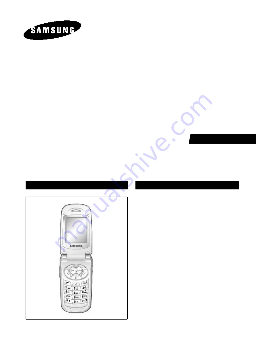
SGH-T208
SERVICE
Manual
China Cellular TDMA Telephon
CONTENTS
1. Exploded Views and Parts List
2. Electrical Parts List
3. Block Diagrams
4. PCB Diagrams
5. Flow Chart of Troubleshooting
CHINA CELLULAR TDMATELEPHONE
Page 1: ...208 SERVICE Manual China Cellular TDMA Telephon CONTENTS 1 Exploded Views and Parts List 2 Electrical Parts List 3 Block Diagrams 4 PCB Diagrams 5 Flow Chart of Troubleshooting CHINA CELLULAR TDMA TELEPHONE ...
Page 2: ...ELECTRONICS Samsung Electronics Co Ltd October 2002 Printed in Korea Code No GH68 03167A BASIC ⓒ ...
Page 3: ...79 C133 C CERAMIC CHIP 0 027nF 5 50V NP0 TP 1005 2 2203 000679 C134 C CERAMIC CHIP 0 027nF 5 50V NP0 TP 1005 2 2203 005482 C135 C CERAMIC CHIP 100nF 10 10V X5R TP 1005 2 2301 001512 C136 C FILM CHIP 3 3NF 5 16V TP 2012 2 2203 000940 C138 C CERAMIC CHIP 470pF 10 50V X7R TP 1005 2 2203 000940 C139 C CERAMIC CHIP 470pF 10 50V X7R TP 1005 2 2203 000812 C140 C CERAMIC CHIP 0 033nF 5 50V NP0 TP 1005 2 2...
Page 4: ...C401 C CERAMIC CHIP 1000nF 80 20 10V Y5V TP 1608 2 2203 005482 C402 C CERAMIC CHIP 100nF 10 10V X5R TP 1005 2 2203 005065 C403 C CERAMIC CHIP 1000nF 80 20 10V Y5V TP 1608 2 2203 005509 C404 C CERAMIC CHIP 330nF 80 20 10V Y5V TP 1005 2 2203 005065 C405 C CERAMIC CHIP 1000nF 80 20 10V Y5V TP 1608 2 2203 005509 C406 C CERAMIC CHIP 330nF 80 20 10V Y5V TP 1005 2 2203 005065 C407 C CERAMIC CHIP 1000nF 8...
Page 5: ...711 005078 CN502 CONNECTOR HEADER NOWALL 34P 2R 0 4MM SMD S AU BLK 2 3722 001456 CN601 JACK PHONE 2P 2 6PI AUF BLK 2 0404 001189 D101 DIODE SCHOTTKY HMPS 2825 15V 1MA MINIPAK TP 2 0401 001033 D301 DIODE SWITCHING MCL4154 25V 200mA M MELF TP 2 2703 002268 L101 INDUCTOR SMD 8 2NH 10 1 0X0 5X0 5MM 2 2703 002309 L102 INDUCTOR SMD 82NH 5 1 0X0 5X0 5MM 2 2703 002198 L103 INDUCTOR SMD 10NH 5 1 0X0 5X0 5M...
Page 6: ... 2007 007008 R133 R CHIP 300OHM 5 1 16W DA TP 1005 2 2007 000172 R134 R CHIP 10ohm 5 1 16W DA TP 1005 2 2007 001156 R135 R CHIP 750ohm 5 1 16W DA TP 1005 2 2007 007134 R136 R CHIP 39Kohm 1 1 16W DA TP 1005 2 2007 000172 R137 R CHIP 10ohm 5 1 16W DA TP 1005 2 2007 000070 R138 R CHIP 0ohm 5 1 16W DA TP 1608 2 2007 001298 R139 R CHIP 51ohm 5 1 16W DA TP 1005 2 2007 007771 R140 R CHIP 0OHM 5 1 16W DA ...
Page 7: ...5 1 16W DA TP 1005 2 2007 000142 R611 R CHIP 2 7Kohm 5 1 16W DA TP 1005 2 2007 000566 R613 R CHIP 220Kohm 5 1 16W DA TP 1005 2 2007 001292 R614 R CHIP 33ohm 5 1 16W DA TP 1005 2 2007 000140 R616 R CHIP 1Kohm 5 1 16W DA TP 1005 2 2007 001339 R618 R CHIP 180Kohm 5 1 16W DA TP 1005 2 2007 007771 R619 R CHIP 0OHM 5 1 16W DA TP 1005 2 2007 007200 R620 R CHIP 2 4OHM 5 1 16W DA TP 1005 2 2909 001186 U100...
Page 8: ... 8 5C 180MW 2 0801 002294 U616 IC CMOS LOGIC 7SH08 AND GATE SSOP 5P 50MIL S 2 1405 001082 V501 VARISTOR 5 6V 20A 1x0 5x0 6mm TP 2 1405 001082 V502 VARISTOR 5 6V 20A 1x0 5x0 6mm TP 2 1405 001082 V503 VARISTOR 5 6V 20A 1x0 5x0 6mm TP 2 1405 001082 V504 VARISTOR 5 6V 20A 1x0 5x0 6mm TP 2 1405 001082 V505 VARISTOR 5 6V 20A 1x0 5x0 6mm TP 2 1405 001082 V506 VARISTOR 5 6V 20A 1x0 5x0 6mm TP 2 1405 00108...
Page 9: ...SAMSUNG Proprietary Contents may change without notice 2 1 2 SGH T208 Exploded View and its Parts List 1 Cellular phone Exploded View 1 2 4 3 5 6 7 8 9 10 11 12 13 14 15 17 18 19 20 21 22 23 16 ...
Page 10: ...GH59 00479A 6 7 FOLDER LOWER GH75 01787A 8 LCD WINDOW GH72 03996A 9 AUTO KEY GH75 01791A 10 FRONT COVER GH75 01786A 11 VOLUME KEY GH75 01792A 12 KEYPAD GH75 01798A 13 MAIN PBA GH82 00122A 14 V KEY ASS Y GH59 00462A 15 METAL DOME SHEET GH59 00370A 16 MIC ASS Y GH59 00536A 17 I F COVER GH73 00741B 18 SHIELD CAN GH75 01977A 19 ANTENNA GH42 00202A 20 REAR COVER GH75 01790A 21 SCREW RF DUMMY GH73 01077...
Page 11: ...SAMSUNG Proprietary Contents may change without notice SGH T208 Exploded view and its Part list 2 3 3 Test Jig GH80 00585A 3 1 Test Jig Cable GH39 00096A 3 2 RF Jig Cable GH39 00140A ...
Page 12: ...SAMSUNG Proprietary Contents may change without notice 2 4 SGH T208 Exploded view and its Part list M ME EM MO O ...
Page 13: ...SAMSUNG Proprietary Contents may change without notice 3 1 3 SGH T208 Block Diagram 1 Block Diagram ...
Page 14: ...SAMSUNG Proprietary Contents may change without notice SGH T208 Block Diagram 3 2 2 RF Block Diagram ...
Page 15: ...SAMSUNG Proprietary Contents may change without notice SGH T208 Block Diagram 3 3 3 Receive Block Diagram ...
Page 16: ...SAMSUNG Proprietary Contents may change without notice SGH T208 Block Diagram 3 4 4 Transmit Block Diagram ...
Page 17: ...05 C506 C507 C509 C510 C512 C513 C514 C515 C519 C520 C521 C522 C525 C527 C530 C547 C598 C599 C601 C611 C612 C613 C614 C615 C616 C618 C619 C620 C621 CN101 CN401 CN501 CN502 CN601 D101 D301 H1 H2 H3 H4 H5 H6 L101 L102 L103 L104 L105 L201 L601 LED301 OSC201 OSC301 Q201 Q202 Q401 Q505 Q506 Q511 R102 R104 R105 R106 R111 R112 R116 R117 R119 R124 R127 R129 R131 R132 R133 R134 R135 R136 R137 R138 R139 R14...
Page 18: ...C607 C608 C609 C610 CENTER CLEAR CN504 DOWN END KEY3 LED504 LED505 LED506 LED508 LED509 LED510 LED511 LED512 LED513 LED514 LED515 LED516 LED517 LED518 LED519 LED520 LED521 LED522 LED524 LED525 LED526 LEFT MANU MIC601 OK Q503 R101 R107 R113 R114 R115 R121 R122 R123 R125 R126 R128 R130 R301 R518 R519 R522 R523 R524 R550 R551 R552 R553 R603 R604 R605 R606 R607 RIGHT SEND SH TP208 TP301 U101 U301 U504...
Page 19: ...100mA POWER ON does not work Check the Voltage more than 3 3V Download again Charge the Battery Check the pin 26 of U401 PMIC is more than 3 2V Check to the path from CN501 to pin 26 of U401 U401 pin 33 2 8V Check the PMIC U401 Check the pin 10 of U401 is high Check the CX805 U302 Check the initial operation END No Yes Yes Yes Yes Yes Yes No No No No ...
Page 20: ...l Failure No No No Check the clock signal s wave at R202 Check the clock generation circuit related to U201 and OSC201 Check the pin 11 of U401 is High Check the PMIC U401 Yes Check the pin 1 of U603 s wave R315 is High Check the IA U201 Check the connections and initialization using Factory Test Program Yes END Yes ...
Page 21: ...xploded view and its Part list 2 3 3 Charging Check the pin 37 of U401 is around 5V Abnormal charging part Check the pin 47 of U401 is LOW Check the TA Check the CN501 Check the pin 20 of U401 is HIGH pin 32 34 of U401 4 7V END No Yes Yes Yes Yes No No Check the U401 ...
Page 22: ...iew and its Part list 4 Sim Check the pin 1 5 of CN401 voltage is 2 8V Phone can t access SIM card Check the CN401 s Connection to SIM card Check the circuit related to U401 Resolder CN401 Check the circuit around U304 Serial EEPROM and data stored in it END No Yes Yes Yes Yes No ...
Page 23: ...nge without notice SGH T208 Exploded view and its Part list 2 5 5 Microphone Part check the connection from MIC601 MicroPhone does not work Resolder MIC600 Audio loopback is enabled by board test program END No Yes Yes Replace the Key PCB ...
Page 24: ... CN502 pin 17 18 sine wave Receiver does not work Check the connection from CN502 to LCD Module Check U201 and speaker related circuit Replace the Flexible PCB Is Speaker working Charge the Battery END No Yes Yes Yes Yes No No Check the voltage on the speaker line lands on LCD Module Replace the Speaker Yes No ...
Page 25: ...SGH T208 Exploded view and its Part list 2 7 7 Speaker Check the Flexible Pcb of Speaker Speaker does not work Check the Pin 6 of U603 1V Resolder the Flexible Pcb Check the U603 END No Yes Yes Yes No The Pin 1 of U603 s Clock 3 9 MHz No Check the U201 Yes ...
Page 26: ...notice 2 8 SGH T208 Exploded view and its Part list 8 Input Check the CN504 s pin2 is HIGH pin3 is LOW pin3 of Key3 is LOW Check Key operation Check U302 using Factory Test Program Resolder CN504 Key3 Change the Front dome sheet END No Yes Yes No Yes ...
Page 27: ...oes not work Check the U504 pin 1 3 3 Charge the Battery Check the U519 END No Yes Yes No Check the CN504 pin 31 is 2 8V Yes Check the U302 Lcd module and Main B d connection is O K Replace the Con to Con Flexible pcb Yes No No Check the U519 pin3 3 3 No Yes Change the U504 Moter s Voltage gap of Lcd module 2 8 Resolder Auto folder Flexible pcb No Yes ...
Page 28: ...Part list 10 Light Backlight ON mode in the menu Backlight does not work pin 22 of CN502 is High Select backlight ON mode Check U302 using Factory Test Program END No Yes Yes No Check the connection from CN502 to LCD Module Yes Replace flexible PCB LCD backlight on Check the LCD Yes Yes No No ...
Page 29: ...iew and its Part list 2 11 11 GSM Receiver CN101 pin 1 3 65dBm RX On RF input 62 CH Amp 50 dBm END U100 pin 11 65dBm U102 pin 11 65dBm Yes No No U100 pin 9 65dBm Yes No Yes No Yes Check R138 C143 L103 CN101 Resolder C140 Check the pin 11 of U100 Check the U100 Check the U102 ...
Page 30: ...d view and its Part list 12 GSM Transmitter CN101 pin 1 3 25dBm Tx On Level 5 Battery voltage 3 8V END U100 pin 11 5 25dBm U102 pin 10 C121 25dBm Yes No No Yes U104 pin 1 7 25dBm No Yes No Yes Check the CN101 Resolder C140 Check the pin 11 of U100 Check the U104 Check the U102 ...
Page 31: ...iew and its Part list 2 13 13 DCS Receiver CN101 pin 1 3 65dBm RX On RF input 62 CH Amp 50 dBm END U100 pin 11 65dBm U102 pin 13 65dBm Yes No No U100 pin 13 65dBm Yes No Yes No Yes Check R138 C143 L103 CN101 Resolder C140 Check the pin 11 of U100 Check the U100 Check the U102 ...
Page 32: ...view and its Part list 14 DCS Transmitter CN101 pin 1 3 25dBm Tx On Level 5 Battery voltage 3 8V END U100 pin 11 1 25dBm U102 pin 12 C132 R140 25dBm Yes No No Yes U104 pin 3 5 25dBm No Yes No Yes Check the CN101 Resolder C140 Check the pin 11 of U100 Check the U104 Check the U102 ...