Samsung SGH-S730i, Service Manual
The Samsung SGH-S730i Service Manual is a comprehensive guide that provides detailed instructions and insights on how to operate and maintain your device. Users can download this manual for free from our website, ensuring they have access to the necessary information whenever needed.
Share
Download


Reviews:
No comments
Related manuals for SGH-S730i

SV8500
Brand: NEC Pages: 2

E500
Brand: QMobile Pages: 13

Yealink SIP-T48G
Brand: Yealink Pages: 2

Yealink SIP-T48G
Brand: Yealink Pages: 4

Yealink SIP-T46G
Brand: Yealink Pages: 38
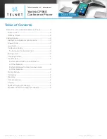
One Talk CP960
Brand: Yealink Pages: 4

One Talk CP960
Brand: Yealink Pages: 20

One Talk CP960
Brand: Yealink Pages: 255

Yealink SIP-T48G
Brand: Yealink Pages: 105

T48G
Brand: Yealink Pages: 13

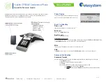
CP860 SERIES
Brand: Yealink Pages: 77
CP860 SERIES
Brand: Yealink Pages: 5
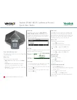
CP930W Telesystem
Brand: Yealink Pages: 2

Yealink SIP-T46G
Brand: Yealink Pages: 8

A24
Brand: Samsung Pages: 139

SS4457
Brand: M4 Pages: 19

iComSL
Brand: DMP Electronics Pages: 46

P160UEU
Brand: Palm Pages: 54


