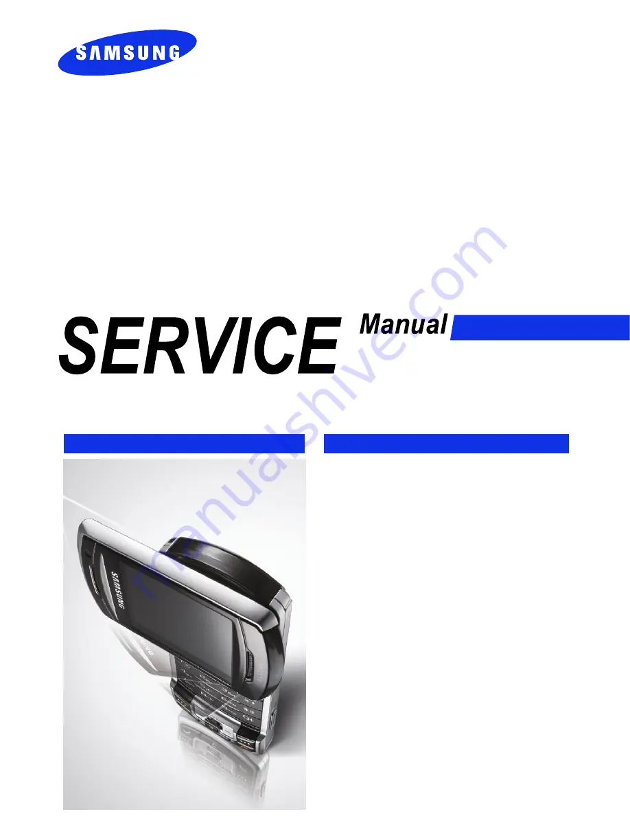
background image

GSM TELEPHONE

SGH-P930

GSM TELEPHONE

CONTENTS

1. Specification

2. Exploded View and Parts list

3. Chart of Troubleshooting

4. Array course control

5. Block Diagrams

6. PCB Diagrams

7. MAIN Electrical Parts List

8. Reference data

9. Safety Precautions

10. Product Function

Summary of Contents for SGH-P930

Page 1: ...EPHONE CONTENTS 1 Specification 2 Exploded View and Parts list 3 Chart of Troubleshooting 4 Array course control 5 Block Diagrams 6 PCB Diagrams 7 MAIN Electrical Parts List 8 Reference data 9 Safety Precautions 10 Product Function ...

Page 2: ...wer ON 3 1 3 1 2 System Initial 3 2 3 1 3 SIM Part 3 5 3 1 4 Charging Part 3 7 3 1 5 Microphone Part 3 10 3 1 6 Speaker Part 3 12 3 1 7 Receiver Part 3 15 3 1 8 Camera Part 3 17 3 1 9 VGA CAMERA Part 3 20 3 1 10 LCD Part 3 22 3 2 RF 3 25 3 2 1 EGSM Receiver 3 25 3 2 2 EGSM Transmitter 3 26 3 2 3 DCS Receiver 3 27 3 2 4 DCS Transmitter 3 28 3 2 5 PCS Receiver 3 29 3 2 6 PCS Transmitter 3 30 3 2 7 U...

Page 3: ... for Downloading 4 2 4 3 S W Downloader Program 4 3 5 Block Diagrams 6 PCB Diagrams 7 MAIN Electrical Parts List 8 Reference data 8 1 Reference Abbreviate 8 1 9 Safety Precautions 9 1 Repair Precaution 9 1 9 2 ESD Electrostaically Sensitive Devices Precaution 9 2 10 Product Function ...

Page 4: ...4 975 1023 512 885 512 810 10562 10838 Tx Rx spacing 45 MHz 95 MHz 80 MHz 190 MHz Mod Bit rate Bit Period 270 833 kbps 3 692 us 270 833 kbps 3 692 us 270 833 kbps 3 692 us 3 84 Mcps s Time Slot Period Frame Period 576 9 us 4 615 ms 576 9 us 4 615 ms 576 9 us 4 615 ms 10 ms Modulation 0 3 GMSK 0 3 GMSK 0 3 GMSK UL 2BPSk DL QPSK MS Power 33 dBm 5 dBm 30 dBm 0 dBm 30 dBm 0 dBm MAX 24 1 3 dBm MIN 50 d...

Page 5: ... dBm 14 15 2 dBm 15 13 2 dBm 16 11 3 dBm 17 9 3dBm 18 7 3 dBm 19 5 3 dBm TX Power control level DCS1800 0 30 3 dBm 1 28 3 dBm 2 26 3 dBm 3 24 3 dBm 4 22 3 dBm 5 20 3 dBm 6 18 3 dBm 7 16 3 dBm 8 14 3 dBm 9 12 4 dBm 10 10 4 dBm 11 8 4 dBm 12 6 4 dBm 13 4 4 dBm 14 2 5 dBm 15 0 5 dBm TX Power control level PCS1900 0 30 3 dBm 1 28 3 dBm 2 26 3 dBm 3 24 3 dBm 4 22 3 dBm 5 20 3 dBm 6 18 3 dBm 7 16 3 dBm ...

Page 6: ...t can not be used without Samsung s authorization 2 1 Cellular phone Exploded View QFR01 QKP01 QKP02 QSH01 QMP01 QAN02 QCA01 QAN01 QRE01 QCR06 QVO01 QSD01 QMO01 QIF01 QCR06 QBA01 QCR12 QVK01 QCR04 QCK01 QFU01 QLC01 QFL01 QSP01 QCA02 QME03 QSP01 QCR26 QCR32 QJK03 QME01 QHI01 QAN05 QAN11 QRF01 QRF02 QSC14 ...

Page 7: ...001850 QFR01 ASSY COVER FRONT GH98 02469A QFU01 ASSY COVER SWING UPPER GH98 02467A QJK03 ASSY KEY JOG GH98 02470A QKP01 ASSY KEYPAD MAIN BLK OPEN GH98 02473A QKP02 ASSY KEYPAD SUB BLK OPEN GH98 02474A QLC01 LCD MODULE SGHP930 GH07 00997A QME01 UNIT SGHP930 KEY PBA GH59 03683A QME03 UNIT SGHP930 CON TO CON GH59 03669A QMO01 MOTOR DC SPHM500 GH31 00242A QMP01 PBA MAIN SGHP930 GH92 03094A QRF01 PMO C...

Page 8: ... 02026A MANUAL USERS TIM ITALIAN GH68 12567A LABEL R MAIN_TIM GH68 13072F BOX P UNIT MAIN SEA_2 GH69 04699K CUSHION CASE TA2 MA2 GH69 04700A MPR BOHO VINYL IF GH74 13606A MPR BOHO VINYL LCD CONN GH74 15350A MPR SPONGE LOWER B GH74 28150A MPR SPONGE MIC GH74 28154A MPR TAPE LEAK L GH74 28552A MPR TAPE LEAK R GH74 28553A MPR INSU TAPE GH74 29175A MPR INSU TAPE GH74 29176A MPR INSU TAPE GH74 29178A M...

Page 9: ...TOR FPCB and VOLUME KEY FPCB take care that FPCB may not be damaged 1 Separate PBA in FRONT 2 Using MOTOR decomposition groove Separate MOTOR in Braket caution 1 When separate take care that CAMERA CONNECTOR FPCB and MOTOR WIRE does not damaged 1 Drain REAR Screw 4 Points 2 Open IF COVER caution 1 take care that it does not happen scratch 1 First dissolution REAR s lower column department locker u...

Page 10: ... take care that it does not happen scratch 1 Separate SWING SCREW 4 POINTs by using tweezers 2 Drain LOWER SCREW 4 POINTs caution 1 take care that it does not happen scratch 1 Separate KEY PBA in FRONT caution 1 take care that it does not happen scratch 1 Separate JOG KEY in KEY PBA 2 Separate SUB KEY in FRONT 3 Separate challenge TAPE in FRONT caution 1 take care that it does not happen scratch ...

Page 11: ...ution 1 Take care so that SPEAKER WIRE may not separate 1 Separate VGA CAMERA and LCD FPCB in LCD ASS Y caution 1 Judge the sepate items are good or not 1 First separate LOWER s left side hook uses a decomposition tool and disjoints remainder hooks 2 Right and left side hook each 3 EAs up and down hook each 1 EA caution 1 take care that it does not happen scratch 1 Separate LOWER and UPPER caution...

Page 12: ...appen scratch 2 take care that LCD FPCB does not interference to the body 1 Contract SCREW 4 POINTs 2 Attach SCREW stack 4 POINTs caution 1 take care that it does not happen scratch 1 Contract VGA CAMERA and LCD FPCB to LCD 2 Attach the Insulation TAPE on the VGA CAMERA CONNECTOR top portion caution 1 Take care damage when insert CAMERA FPCB 1 Insert LCD ASS y to UPPER 2 Insert Both SPEAKER like a...

Page 13: ...Observe to JOG KEY wrong contract 1 Contract KEY PBA ASS Y to FRONT 2 Attach challenge TAPE on FRONT left side lower column caution 1 take care that it does not happen scratch 2 KEY PAD is lacking accordantly with FRONT 1 Combine PBA and Intenna Braket 2 Combine MOTOR in Intenna department caution 1 Take care that CAMERA FPCB and MOTOR WIRE does not go damaged 1 Contract LCD CONNECTOR after combin...

Page 14: ...arts List 2 9 This Document can not be used without Samsung s authorization 9 10 1 Contract REAR to FRONT ASS Y In order such as picture caution 1 take care that it does not happen scratch 1 Contract to SCREW 4 POINTs caution 1 take care that it does not happen scratch LOCKER ...

Page 15: ...k the current consumption Current consumption 100mA Down load again Voltage 3 3V R509 2 4V Check the Clock at OSC500 32kHz END Charge the Battery Check the PMIC related to PS_HOLD NO NO NO YES YES YES Resolder OSC 500 NO YES Check the PMIC U500 NO Check U500 C511 MSMP_2 6V 2 6V C513 MSMC_1 375 1 375V C512 MSMA_2 6V 2 6V C514 MSME_1 8V 1 8V YES Check the clock at TCX800 19 2MHz YES check the clock ...

Page 16: ...s authorization 3 1 2 System Initial Check the clock signal s at R504 Check the Sleep X tal signal s at C519 YES NO NO YES YES YES NO NO NO YES Check the Audio part Check the LCD part Check the OSC500 END Sound operation OK LCD Display OK Initial Failure The pin 9 of U500 Low High Check the clock generation circuit related to U501 and TCX800 Check the U500 ...

Page 17: ...VREG_RFRX1 69 VREG_RFRX2 67 VDD_MSME 35 VDD_PA 29 71 VDD_RF 41 VDD_RUIM 77 VDD_SPKR VDD_WLAN 65 25 VIB_DRV_N VREG_5V 12 USB_SE0 USB_VBUS 16 VBACKUP 48 VBAT 6 VCHG 2 VCOIN 60 VDD_ANA 54 VDD_MAIN 83 VDD_MSM 52 33 VDD_MSMC 75 TCXO_EN 55 TCXO_IN 58 TCXO_OUT 53 15 USB_CTL_N USB_DAT 17 USB_D_M 20 USB_D_P 18 USB_ID 11 13 USB_OE_N 19 RUIM_RST 43 49 SBCK SBDT 47 SBST 51 SLEEP_CLK 45 SPKR_BYP 74 78 SPKR_IN_...

Page 18: ...SAMSUNG Proprietary Contents may change without notice Flow Chart of Troubleshooting and Circuit Diagrams 3 4 This Document can not be used without Samsung s authorization ...

Page 19: ...ument can not be used without Samsung s authorization 3 1 3 SIM Part Check the voltage at SIM500 pin 1 2 8V Check the U500 UCP100 Please insert SIM card Check the SIM500 s Connection to SIM card END Check the SIM Card Resolder or change SIM500 YES Check the U500 There is any signal pin 2 3 4 of SIM500 YES YES NO NO NO ...

Page 20: ...ce Flow Chart of Troubleshooting and Circuit Diagrams 3 6 This Document can not be used without Samsung s authorization USIM_2 85V NC 10 1 VCC 2 VCC 5 VPP SIM500 CLK 3 GND 4 I O 6 NC 7 8 NC 9 NC R509 C539 C543 C542 C541 C540 USIM_DATA USIM_CLK USIM_RESET ...

Page 21: ...7 This Document can not be used without Samsung s authorization 3 1 4 Charging Part Check the pin 13 14 of IFC200 3 3V Again check the IFC200 Abnormal charging operation YES NO Check the pin 3 of BTC200 3 3V NO See the indicator of charger is red YES YES NO Check the path of IFC200 and BTC200 Check the TC END ...

Page 22: ...6 7 7 8 8 9 9 21 NC NC 22 NC 23 24 NC NC5 25 18 18 19 19 2 2 20 20 3 3 4 4 5 5 6 6 10 10 11 11 12 12 13 13 14 14 15 15 16 16 17 17 IFC200 1 1 TDZ5 6 R208 R209 ZD202 1 2 3 4 5 6 3 0 2 D Z VR205 VR201 R202 R217 VR204 R200 C218 R207 R206 TA200 C216 C206 C217 C212 L204 R220 C231 BOOT_SW R210 C234 C233 C232 R215 C207 C200 C203 VR200 1 0 2 D Z 0 0 2 D Z R218 C219 L202 VBAT R203 9 0 2 D Z R214 TA204 ACC_...

Page 23: ...SAMSUNG Proprietary Contents may change without notice Flow Chart of Troubleshooting and Circuit Diagrams 3 9 This Document can not be used without Samsung s authorization ...

Page 24: ...n not be used without Samsung s authorization 3 1 5 Microphone Part The voltage of C214 is 2 3V YES YES YES YES NO NO NO Micro phone does not work Is the assembled status of Microphone O K Reassemble the microphone Check the DC bias voltage on Mic path Check the path around MIC Bias circuit The microphone is OK Check UCP100 END ...

Page 25: ...ut notice Flow Chart of Troubleshooting and Circuit Diagrams 3 11 This Document can not be used without Samsung s authorization C222 C221 C214 R201 C209 C220 MICBIAS_2 85V L203 TA201 C211 C205 L205 R204 R205 C215 C213 C223 C210 MIC200 MIC1P MIC1N ...

Page 26: ...aker Part There is no sound from speaker Replace the Speaker Check the U302 END The terminal of Speaker is OK There is signal U302 pin 2 There is signal U304 R331 Check the U304 Check the UCP100 The type of sound from the Speaker is Melody Check the U300 Are there any signal at the pin 12 24 of U304 The type of sound from the Speaker is Media File NO NO NO NO NO YES YES YES YES YES ...

Page 27: ... RCVP ICE_AMP_OUT_N_L RCVN ICE_AMP_OUT_N_R RCVN ICE_AMP_OUT_P_R RCVP SPKL SPKR SPKR SPKR_SEL C324 L301 C316 VBAT C322 R316 C323 L300 R318 C326 R317 L303 27 VDD 4 VOMR 5 VSS 6 VOPR VDD 8 VSS VDD 2 VSS 20 VSS 21 VDD 22 VIML 23 VREFL 24 VIPL GND 25 26 NC NC 12 VIPR 13 EN_R 14 VSS 15 VDD 16 VOML 17 VSS 18 VOPL 19 VDD U304 EN_L 10 VIMR 11 VREFR R313 R327 R310 R308 C313 C314 C312 C320 R331 R314 R325 C34...

Page 28: ...P S 17 18 2 T U O P S SPVDD 15 16 SPVSS 7 D D V F E R V 9 G G 34 G 35 G 36 10 HPOUT L MONO HPOUT R 11 32 IOVDD 2 D E L R T M 19 3 D 4 D 23 5 D 22 6 D 21 20 7 D 12 EQ1 EQ2 13 14 EQ3 33 U300 A0 30 I K L C 1 27 D0 D1 26 2 D 25 24 C317 C311 R307 YMU_2 8V C306 C319 C336 C307 C337 EBI2_D 0 EBI2_D 1 YMU_CS_N YAMA_OUT_R TCXO_OUT YMU_IRQ RESET_OUT YAMA_OUT_L 2 D _ 2 I B E 3 D _ 2 I B E 4 D _ 2 I B E 5 D _ ...

Page 29: ...s authorization 3 1 7 Receiver Part Is the terminal of receiver is ok NO Replace the receiver NO Check the UCP100 and speaker related circuit There is no sound from receiver YES YES Are there any signal at the pin 1 of U308 U309 YES Is receiver working YES END Replace the receiver NO NO Check the U308 U309 and soldering Are there any signal at the R135 R132 ...

Page 30: ...Troubleshooting and Circuit Diagrams 3 16 This Document can not be used without Samsung s authorization R329 3 4 B0 6 B1 GND 5 1 S VCC 2 5 GND S 1 2 VCC U309 A U308 A 3 B0 4 B1 6 VBAT R330 ICEAMP_EN RCVN RCV_N RCV_P RCVP R132 R135 C144 VOICE_OUT_P VOICE_OUT_N RCV_N RCV_P ...

Page 31: ...ung s authorization 3 1 8 Camera Part Camera function does not work Check the connect HEA201 NO Connect the HEA201 Check the condition of Soldering F200 F203 F208 F209 NO NO Check U200 Pin 9 2 8v Pin 10 1 5v NO END YES YES YES Resolder or change F200 F203 F208 F209 Check UCP100 MSM6275 Resolder or change U200 YES Check U200 Pin 2 3 2 6v C238 MCLK 33MHz ...

Page 32: ...AM_1 5V CAM_2 8V C228 C229 C241 R219 C238 C236 C243 C242 C239 TP200 C237 L206 7 7 8 8 9 9 NC 25 26 NC 21 22 22 23 23 24 24 3 3 4 4 5 5 6 6 14 14 15 15 16 16 17 17 18 18 19 19 2 2 20 20 21 HEA201 1 1 10 10 11 11 12 12 13 13 C240 PCLK CAM_RESET_N VF_YUV 0 VF_YUV 1 VF_YUV 2 VF_YUV 3 VF_YUV 4 VF_YUV 5 VF_YUV 7 VF_YUV 6 VSYNC HSYNC CAM_SCL MEGA_STBY MCLK CAM_SDA 7 VIN 1 10 VOUT1 VOUT2 9 C258 11 12 D N ...

Page 33: ...SAMSUNG Proprietary Contents may change without notice Flow Chart of Troubleshooting and Circuit Diagrams 3 19 This Document can not be used without Samsung s authorization ...

Page 34: ... Part YES NO NO NO NO YES YES YES YES VGA CAMERA FUNCTION does not work Check CN2 of LCD Circuit Check the condition of soldering F200 F203 F208 F209 Connect the CN2 Resolder or change Check U201 VGA Cam enable Pin 6 2 6V Pin 27 of HEA202 33MHz MCLK Check Pin 29 of HEA202 33MHz PCLK Resolder R226 or Check U100 Change VGA CAM module Check U201 Pin 3 1 8V NO Resolder or Change U201 YES END ...

Page 35: ...ents may change without notice Flow Chart of Troubleshooting and Circuit Diagrams 3 21 This Document can not be used without Samsung s authorization NC 1 VDD VOUT 3 R226 U201 6 CE GND 2 GND 5 4 C252 VBAT C260 CAM_1 8V CAM_EN2 ...

Page 36: ...1 10 LCD Part YES YES Check VR203 YES Check HEA202 LCD Connector LCD does not work NO Connect HEA202 Check HEA202 Backlight enabld Pin 24 2 6V Check R228 U100 Backlight enable path Check C47 of LCD circuit 11V NO YES YES LDI is dead Change LCD main FPCB LCD Backlight on NO NO Check HEA202 Pin 12 3V Pin 14 2 6V NO Check U500 PM6550 Resolder J1 J3 connecotor of LCD Circuit END ...

Page 37: ... 13 14 14 15 15 16 16 17 17 18 18 19 19 2 2 20 20 HEA202 1 1 10 10 11 11 12 12 1 0 1 2 3 4 8 7 6 5 9 F206 TA205 C249 R224 C248 R228 C246 2 3 4 8 7 6 5 9 8 7 6 5 9 F204 1 0 1 F202 1 0 1 2 3 4 F205 1 0 1 2 3 4 8 7 6 5 9 1 0 1 2 3 4 8 7 6 5 9 F207 C245 TP201 MSMP_2 6V VBAT CAM_1 8V VLCD_3 0V 3 0 2 R V LCD_RESET F_YUV 3 F_YUV 1 CAM_SCL CAM_SDA MCLK PCLK VGA_STBY FMARK LCD_D 14 LCD_D 12 LCD_D 10 LCD_D ...

Page 38: ...SAMSUNG Proprietary Contents may change without notice Flow Chart of Troubleshooting and Circuit Diagrams 3 24 This Document can not be used without Samsung s authorization LCD Main Fpcb LCD Main Fpcb ...

Page 39: ...t Samsung s authorization 3 2 RF 3 2 1 EGSM Receiver Continuous RX ON RF Input 62 CH AMP 50dBm NO U802 Check Pin 3 4 55dBm Check intenna soldering D800 Resolder or Change NO NO Check the path of F800 and U600 NO NORMAL CONDITION Catch the channel YES D800 Check Pin 12 13 55dBm U600 Check Pin 37 38 55dBm U802 Resolder or Change THE END YES YES YES ...

Page 40: ...ment can not be used without Samsung s authorization 3 2 2 EGSM Transmitter YES NO Check the U802 THE END NO YES VCO600 Resolder or change NO YES NO Tx ON Level 5 battery voltage 3 8V U802 Check Pin 3 4 30dBm D800 Check Pin 22 30dBm U600 Check Pin 40 2 3V D800 Resolder or Change YES Check the U600 VCO600 Check Pin 1 6dBm ...

Page 41: ...ithout Samsung s authorization 3 2 3 DCS Receiver YES U802 Check Pin 3 4 55dBm D800 Check Pin 14 15 55dBm U600 Check Pin 34 35 55dBm Check antenna contack U802 Resolder or Change D800 Resolder or Change THE END NO NO YES YES YES Check the path of D800 and U600 NO Continuous RX ON RF Input 698 CH AMP 50dBm NORMAL CONDITION Catch the channel NO ...

Page 42: ...ment can not be used without Samsung s authorization 3 2 4 DCS Transmitter Check the U600 NO Tx ON Level 0 battery voltage 3 8V U802 Check Pin 3 4 27dBm YES NO D800 Check Pin 20 27dBm U600 Check Pin 40 2 3V Check the U802 D800 Resolder or Change THE END NO YES YES VCO600 Check Pin 5 6dBm VCO600 Resolder or change YES NO ...

Page 43: ...Receiver NO NO NO NO Check antenna contack Continuous RX ON RF Input 698 CH AMP 50dBm YES CON800 Resolder or Change THE END YES YES YES Continuous RX ON RF Input 698 CH AMP 50dBm NORMAL CONDITION Catch the channel U802 Check Pin 3 4 55dBm D800 Check Pin 16 17 55dBm U600 Check Pin 24 25 55dBm U802 Resolder or Change D800 Resolder or Change YES YES YES Check the path of D800 and U600 ...

Page 44: ...ment can not be used without Samsung s authorization 3 2 6 PCS Transmitter NO Tx ON Level 0 battery voltage 3 8V U802 Check Pin 3 4 27dBm YES NO D800 Check Pin 20 27dBm U600 Check Pin 40 2 3V Check the U802 D800 Resolder or Change THE END NO YES YES Check the U600 VCO600 Check Pin 5 6dBm VCO600 Resolder or change YES NO ...

Page 45: ...C616 R619 R614 C624 C622 TA600 R605 R607 C629 RFTX_2 85V TX_VCO_1_EN TX_VCO_0_EN MOD_CP DCSTX_IN GSMTX_IN TXVCO 17 UMTS2100 4 V1 9 10 V2 V3 11 8 VDD 7 18 G G 19 21 G 23 G G 24 3 NC PCS_RX 16 PCS_RX DCS_RX DCS PCS_TX 20 12 EGSM_RX EGSM_RX 13 22 EGSM_TX 1 G G 2 5 G G D800 ANT 6 14 DCS_RX 15 L812 L811 L810 C816 C818 L807 L809 L806 L804 C817 5 5 6 6 ANT801 1 1 2 2 3 3 4 4 1 1 2 2 3 3 4 4 5 5 6 6 ANT80...

Page 46: ...51 UMTS2100_OUT 55 UMTS800_OUT 49 VCONTROL 9 E N U T _ O C V 33 S A I B _ R 44 SBCK 45 SBDT 46 SBST 6 O X C T 19 TX_IN 18 TX_IP 40 P C _ D O M _ X T 58 NC1 59 NC2 47 RF_ON 14 N I _ X R 13 P I _ X R 12 N Q _ X R 11 P Q _ X R 32 N I _ O C V _ X R 34 N N I _ 0 0 8 1 M S G 35 P N I _ 0 0 8 1 M S G 24 GSM1900_INN 25 GSM1900_INP 21 GSM850_INN 22 GSM850_INP 38 N N I _ 0 0 9 M S G 37 P N I _ 0 0 9 M S G 2...

Page 47: ...SAMSUNG Proprietary Contents may change without notice Flow Chart of Troubleshooting and Circuit Diagrams 3 33 This Document can not be used without Samsung s authorization ...

Page 48: ...H AMP 40dBm NORMAL CONDITION Catch the channel YES NO U802 Check Pin 3 4 45dBm D800 Check Pin 4 45dBm U700 Check Pin 18 65dBm Check antenna contack U802 Resolder or Change D800 Resolder or Change THE END NO NO YES YES YES U700 Resolder or change DUF700 Check Pin 5 45dBm DUF700 Resolder or change NO YES NO Change the path of F700 and U700 U700 check pin 8 9 65dBm F700 check pin 3 4 65dBm YES YES NO...

Page 49: ...itter Tx ON RF output 9750 CH OUT PWR 24dBm U802 Check Pin 3 4 22dBm YES NO D800 Check Pin 4 22dBm DUF700 Check Pin 11 20dBm PAM700 Check Pin 1 20 15dBm U802 Resolder or Change D800 Resolder or Change DUF700 Resolder or Change THE END NO NO YES YES PAM700 Resolder or change NO F600 Resolder or change U600 Resolder or change YES YES YES NO NO F600 check pin 1 4 20dBm U600 check pin 51 20dBm ...

Page 50: ...M 6 GMIXP GND1 4 9 4 2 D N G 35 GPS_TUNE 9 3 2 BLANK 29 CP_DUMP CP_OUT 30 31 FAQ 8 4 U700 TCXO_2 85V R704 C726 C729 C728 L708 TCXO_2 85V TCXO_2 85V C744 C723 C721 TCXO_2 85V C743 C736 C737 C738 L705 R707 C727 C734 1 IN OUT 3 4 OUT F700 G 2 5 G C745 R708 C730 R705 L707 C746 P Q _ X R M Q _ X R P I _ X R M I _ X R K C B S T S B S T D B S TCXO N I A N L _ S T M U UMTS_RX_VCO_IN UMTS_RXM UMTS_RXP UMTS...

Page 51: ... Contents may change without notice Flow Chart of Troubleshooting and Circuit Diagrams 3 37 This Document can not be used without Samsung s authorization 5 G IN 1 OUT 4 F600 2 G 3 G C605 L601 C606 C604 UMTSTX_IN UMTS_TXRF ...

Page 52: ...horization R805 Resolder or change 3 2 9 BLUETOOTH Has the ANT800 BT Ant no crack Pin 3 of U800 3 0V YES YES NO NO ANT800 BT Ant Resolder or Change Check the U800 There is any signal Pin 20 of U800 YES Is there no problem of doing BT activation YES THE END NO NO UCP100 Resolder or Change Check the U800 Bluetooth does not work Check U800 Pin 22 output 6dBm YES NO ...

Page 53: ...6V WLAN TX UART_RTS 9 UART_RXD UART_TXD 8 C D D V 2 5 1 O D D V 1 F R D D V 24 VREGCTL 3 VREGIN 7 LINK STATUS PCM_CLK 14 PCM_IN 16 11 PCM_OUT PCM_SYNC 10 22 RF_OUT RST_N 23 UART_CTS 18 19 D N G 5 2 6 2 D N G D N G 7 2 8 2 D N G 1 2 D N G 5 D N G 7 1 D N G HOSTWAKE 6 13 U800 BT_WAKE 20 BT TX 12 EXT_LPO 4 L813 C807 R806 AUX_PCM_DIN BT_CONTROL AUX_PCM_CLK AUX_PCM_DOUT AUX_PCM_SYNC BT_CTS BT_TXD BT_RX...

Page 54: ...t the time to local time NO YES Check OSC1000 C1035 C1028 Check U1000 Resolder or Change NO NO YES Check U1001 Resolder or Change YES Check OSC1001 C1000 C1002 NO THE END YES Is displayed time on the phone correct Check pin 9 10 of U1001 Is it about 36MHz Check pin A4 B4 of U1000 Is it about 30MHz Is there any signal pin 16 17 18 19 of U1001 when operating DVB H Is there any signal pin 8 of U1001 ...

Page 55: ...BUS0 P9 SRAM_BUS2 R10 SRAM_BUS4 R11 SRAM_BUS7 R12 SRAM_BUS10 R13 SRAM_BUS13 R14 SRAM_BUS15 P11 SRAM_BUS8 P12 SRAM_BUS11 P13 SRAM_BUS14 P15 SRAM_BUS16 6 N S S V 7 N S S V 8 N S S V N9 SRAM_BUS3 P10 SRAM_BUS5 N10 SRAM_BUS6 N11 SRAM_BUS9 N12 SRAM_BUS12 N14 SRAM_BUS17 N15 SRAM_BUS18 2 L S S V M13 SRAM_BUS19 M14 SRAM_BUS20 M15 SRAM_BUS21 2 K S S V 3 K S S V L13 SRAM_BUS22 L14 SRAM_BUS23 3 H S S V 1 J S...

Page 56: ...SAMSUNG Proprietary Contents may change without notice Flow Chart of Troubleshooting and Circuit Diagrams 3 42 This Document can not be used without Samsung s authorization ...

Page 57: ...G Proprietary Contents may change without notice 4 Array course control 4 1 This Document can not be used without Samsung s authorization Test Jig GH80 03308A Test Cable GH39 00706A RF Test Cable GH39 00222A ...

Page 58: ...ent can not be used without Samsung s authorization 4 1 Downloading Binary Files 1 Swift Model firmware is composed of 2 files NAV05_TIM folder Main source code binary SECUMTS_rsc resource file 4 2 Prerequisite Downloader program MSM6275 U Medic_v1 3 P930 Moblie Phone Data Cable Binary Files ...

Page 59: ...uthorization 4 3 S W Downloader Program 1 Load the binary download program by execution the MSM6275 U Medic_v1 3 exe 2 Press key 4 and connect D L cable enter the D L mode click the binary button and Select the bin NAV05_TIM Check Erase NAND Change Boot Area Code Set the everything else as the default values which are shown below ...

Page 60: ...nished successfully there is a Disconnected COM portl message After Binary downloading press key 4 and connect D L cable again click the Resource button and select SECUMTS_rse bin and click the Download button 5 After finishing downloading Certain memory resets should be done to guarantee the normal performance 6 Custom reset 2767 2878 and press key 1 Factory preconfiguration 01010522 and press ke...

Page 61: ...SAMSUNG Proprietary Contents may change without notice 5 Block Diagrams 5 1 This Document can not be used without Samsung s authorization ...

Page 62: ... F 2 0 2 F 3 0 2 F 4 0 2 F 5 0 2 F 6 0 2 F 7 0 2 F 8 0 2 F 9 0 2 F 0 0 6 F 0 0 2 A E H HEA201 HEA202 IFC200 0 0 0 1 C S O OSC500 PAM700 1 0 5 Q RFS1000 SIM500 5 0 2 A T TA206 TA502 TA503 0 0 6 A T TA700 TA701 TP1010 TP108 TP111 TP113 TP115 TP116 TP200 TP201 TP415 TP902 0 0 2 R T N O C _ T 1 0 0 1 U 0 0 4 U U403 U500 0 0 6 U U701 U800 2 0 8 U 2 0 9 U 3 0 9 U VCO600 0 0 2 R V 1 0 2 R V 2 0 2 R V VR2...

Page 63: ...905 TA906 0 0 8 X C T TP100 TP1000 TP1001 TP1002 TP1003 TP1004TP1005 TP1006 TP1007 TP1008 TP1009 TP101 TP1011 TP1012 TP102 TP103 TP104 TP105 TP106 TP107 TP109 TP110 TP114 TP300 TP400 TP401 TP402 TP403 TP405 TP406 TP407 TP408 TP409 TP410 TP411 TP412 TP413 TP414 TP900 TP901 TP903 TP904 TP905 0 0 0 1 U U101 2 0 1 U 0 0 2 U U201 2 0 2 U 0 0 3 U U302 3 0 3 U 4 0 3 U U305 U308 U309 U401 2 0 4 U 2 0 5 U ...

Page 64: ... DIODE TVS SNA 0406 001237 ZD207 DIODE TVS SNA 0406 001239 D1000 DIODE TVS SA 0406 001254 ZD203 DIODE TVS SA 0406 001254 ZD400 DIODE TVS SA 0407 001002 ZD500 DIODE ARRAY SA 0504 001113 Q101 TR DIGITAL SA 0504 001113 Q501 TR DIGITAL SA 0505 001518 TR200 FET SILICON SA 0801 002995 U402 IC CMOS LOGIC SA 0902 002113 U900 IC MICROPROCESSOR SA 1001 001231 U202 IC ANALOG SWITCH SA 1001 001265 U308 IC ANA...

Page 65: ... IC POWER SUPERVISOR SA 1203 004518 U401 IC BATTERY SA 1204 002138 U300 IC MELODY SA 1204 002625 U1000 IC DECODER SA 1205 002645 U600 IC TRANSCEIVER SA 1205 002781 U700 IC RECEIVER SA 1205 002790 UCP100 IC MODEM SA 1209 001577 U701 IC DETECTOR SA 1404 001224 U101 THERMISTOR NTC SA 1405 001082 VR200 VARISTOR SA 1405 001082 VR201 VARISTOR SA 1405 001082 VR203 VARISTOR SA 1405 001082 VR204 VARISTOR S...

Page 66: ... SA 2007 000148 R413 R CHIP SA 2007 000149 R223 R CHIP SA 2007 000151 R308 R CHIP SA 2007 000154 R404 R CHIP SA 2007 000157 R221 R CHIP SA 2007 000162 R506 R CHIP SA 2007 000163 R1031 R CHIP SA 2007 000169 R402 R CHIP SA 2007 000170 R1000 R CHIP SA 2007 000170 R122 R CHIP SA 2007 000170 R138 R CHIP SA 2007 000171 R1017 R CHIP SA 2007 000171 R206 R CHIP SA 2007 000171 R207 R CHIP SA 2007 000171 R22...

Page 67: ... SA 2007 001119 R201 R CHIP SA 2007 001292 R1024 R CHIP SA 2007 001292 R612 R CHIP SA 2007 001298 R619 R CHIP SA 2007 003001 R132 R CHIP SA 2007 003001 R135 R CHIP SA 2007 007009 R923 R CHIP SA 2007 007015 R406 R CHIP SA 2007 007136 R600 R CHIP SA 2007 007142 R327 R CHIP SA 2007 007142 R328 R CHIP SA 2007 007142 R903 R CHIP SA 2007 007142 R904 R CHIP SA 2007 007142 R906 R CHIP SA 2007 007142 R908 ...

Page 68: ...P SA 2007 007528 R703 R CHIP SA 2007 007627 R1020 R CHIP SA 2007 007741 R502 R CHIP SA 2007 007766 R109 R CHIP SA 2007 007766 R918 R CHIP SA 2007 007766 R919 R CHIP SA 2007 007875 R921 R CHIP SA 2007 008040 R233 R CHIP SA 2007 008040 R234 R CHIP SA 2007 008040 R235 R CHIP SA 2007 008040 R236 R CHIP SA 2007 008040 R237 R CHIP SA 2007 008040 R238 R CHIP SA 2007 008040 R239 R CHIP SA 2007 008040 R240...

Page 69: ...HIP SA 2007 008055 R209 R CHIP SA 2007 008055 R227 R CHIP SA 2007 008055 R403 R CHIP SA 2007 008055 R407 R CHIP SA 2007 008055 R416 R CHIP SA 2007 008055 R417 R CHIP SA 2007 008055 R508 R CHIP SA 2007 008055 R511 R CHIP SA 2007 008056 R1003 R CHIP SA 2007 008057 R917 R CHIP SA 2007 008213 R601 R CHIP SA 2007 008354 R922 R CHIP SA 2007 008419 R130 R CHIP SA 2007 008419 R211 R CHIP SA 2007 008419 R2...

Page 70: ...007 008516 R318 R CHIP SA 2007 008516 R401 R CHIP SA 2007 008516 R408 R CHIP SA 2007 008516 R415 R CHIP SA 2007 008516 R510 R CHIP SA 2007 008531 R706 R CHIP SA 2007 008531 R707 R CHIP SA 2007 008542 R1004 R CHIP SA 2007 008542 R1005 R CHIP SA 2007 008542 R1006 R CHIP SA 2007 008542 R101 R CHIP SA 2007 008542 R1011 R CHIP SA 2007 008542 R1012 R CHIP SA 2007 008542 R1013 R CHIP SA 2007 008542 R1016...

Page 71: ...P SA 2007 008542 R302 R CHIP SA 2007 008542 R312 R CHIP SA 2007 008542 R409 R CHIP SA 2007 008542 R512 R CHIP SA 2007 008542 R513 R CHIP SA 2007 008542 R514 R CHIP SA 2007 008542 R515 R CHIP SA 2007 008542 R702 R CHIP SA 2007 008542 R900 R CHIP SA 2007 008542 R901 R CHIP SA 2007 008542 R905 R CHIP SA 2007 008542 R924 R CHIP SA 2007 008542 R925 R CHIP SA 2007 008581 R605 R CHIP SNA 2007 008581 R606...

Page 72: ...R1002 R CHIP SA 2007 009212 R701 R CHIP SA 2203 000233 C500 C CER CHIP SA 2203 000233 C817 C CER CHIP SA 2203 000254 C129 C CER CHIP SA 2203 000254 C303 C CER CHIP SA 2203 000254 C720 C CER CHIP SA 2203 000278 C211 C CER CHIP SA 2203 000278 C220 C CER CHIP SA 2203 000278 C935 C CER CHIP SA 2203 000311 C624 C CER CHIP SA 2203 000330 C1028 C CER CHIP SA 2203 000330 C1035 C CER CHIP SA 2203 000330 C7...

Page 73: ...R CHIP SA 2203 000812 C703 C CER CHIP SA 2203 000836 C627 C CER CHIP SA 2203 000854 C1027 C CER CHIP SA 2203 000854 C215 C CER CHIP SA 2203 000854 C221 C CER CHIP SA 2203 000854 C801 C CER CHIP SA 2203 000995 C612 C CER CHIP SA 2203 000995 C613 C CER CHIP SA 2203 001072 C705 C CER CHIP SA 2203 001072 C709 C CER CHIP SA 2203 001072 C724 C CER CHIP SA 2203 001124 C746 C CER CHIP DNA 2203 001153 C713...

Page 74: ... CHIP SA 2203 005138 C314 C CER CHIP SA 2203 005138 C315 C CER CHIP SA 2203 005281 C725 C CER CHIP SA 2203 005281 C732 C CER CHIP SA 2203 005393 C604 C CER CHIP SA 2203 005571 C544 C CER CHIP SA 2203 005682 C541 C CER CHIP SA 2203 005682 C542 C CER CHIP SA 2203 005682 C543 C CER CHIP SA 2203 005682 C608 C CER CHIP SA 2203 005682 C620 C CER CHIP SA 2203 005682 C707 C CER CHIP SA 2203 005682 C803 C ...

Page 75: ... 2203 005806 C113 C CER CHIP SNA 2203 005806 C114 C CER CHIP SNA 2203 005806 C115 C CER CHIP SNA 2203 005806 C119 C CER CHIP SNA 2203 005806 C317 C CER CHIP SNA 2203 005806 C323 C CER CHIP SNA 2203 005806 C324 C CER CHIP SNA 2203 005806 C325 C CER CHIP SNA 2203 005806 C326 C CER CHIP SNA 2203 005806 C406 C CER CHIP SNA 2203 005806 C502 C CER CHIP SNA 2203 005806 C503 C CER CHIP SNA 2203 005806 C51...

Page 76: ...HIP SA 2203 006048 C739 C CER CHIP SA 2203 006194 C121 C CER CHIP SA 2203 006194 C146 C CER CHIP SA 2203 006194 C250 C CER CHIP SA 2203 006194 C408 C CER CHIP SA 2203 006194 C410 C CER CHIP SA 2203 006194 C522 C CER CHIP SA 2203 006194 C700 C CER CHIP SA 2203 006194 C714 C CER CHIP SA 2203 006194 C715 C CER CHIP SA 2203 006194 C716 C CER CHIP SA 2203 006194 C812 C CER CHIP SA 2203 006260 C230 C CE...

Page 77: ...HIP SA 2203 006423 C1012 C CER CHIP SA 2203 006423 C1013 C CER CHIP SA 2203 006423 C1014 C CER CHIP SA 2203 006423 C1015 C CER CHIP SA 2203 006423 C1018 C CER CHIP SA 2203 006423 C1019 C CER CHIP SA 2203 006423 C1020 C CER CHIP SA 2203 006423 C1021 C CER CHIP SA 2203 006423 C1023 C CER CHIP SA 2203 006423 C1024 C CER CHIP SA 2203 006423 C1025 C CER CHIP SA 2203 006423 C1029 C CER CHIP SA 2203 0064...

Page 78: ... CHIP SA 2203 006423 C319 C CER CHIP SA 2203 006423 C407 C CER CHIP SA 2203 006423 C409 C CER CHIP SA 2203 006423 C509 C CER CHIP SA 2203 006423 C521 C CER CHIP SA 2203 006423 C534 C CER CHIP SA 2203 006423 C540 C CER CHIP SA 2203 006423 C614 C CER CHIP SA 2203 006423 C616 C CER CHIP SA 2203 006423 C702 C CER CHIP SA 2203 006423 C727 C CER CHIP SA 2203 006423 C736 C CER CHIP SA 2203 006423 C737 C ...

Page 79: ...R CHIP SA 2203 006562 C1034 C CER CHIP SA 2203 006562 C109 C CER CHIP SA 2203 006562 C118 C CER CHIP SA 2203 006562 C143 C CER CHIP SA 2203 006562 C228 C CER CHIP SA 2203 006562 C244 C CER CHIP SA 2203 006562 C245 C CER CHIP SA 2203 006562 C246 C CER CHIP SA 2203 006562 C248 C CER CHIP SA 2203 006562 C249 C CER CHIP SA 2203 006562 C300 C CER CHIP SA 2203 006562 C302 C CER CHIP SA 2203 006562 C305 ...

Page 80: ...HIP SA 2203 006562 C634 C CER CHIP SA 2203 006562 C726 C CER CHIP SA 2203 006562 C743 C CER CHIP SA 2203 006562 C813 C CER CHIP SA 2203 006562 C920 C CER CHIP SA 2203 006562 C921 C CER CHIP SA 2203 006562 C922 C CER CHIP SA 2203 006562 C927 C CER CHIP SA 2203 006562 C928 C CER CHIP SA 2203 006617 C134 C CER CHIP SA 2203 006617 C137 C CER CHIP SA 2203 006648 C717 C CER CHIP SA 2203 006674 C601 C CE...

Page 81: ...P SA 2203 006838 C510 C CER CHIP SA 2203 006838 C515 C CER CHIP SA 2203 006838 C516 C CER CHIP SA 2203 006838 C529 C CER CHIP SA 2203 006838 C530 C CER CHIP SA 2203 006838 C531 C CER CHIP SA 2203 006838 C532 C CER CHIP SA 2203 006838 C533 C CER CHIP SA 2203 006838 C807 C CER CHIP SA 2203 006838 C936 C CER CHIP SA 2203 006838 C937 C CER CHIP SA 2301 001200 C625 C FILM SMD PPS SA 2301 001213 C602 C ...

Page 82: ...003 INDUCTOR SMD SA 2703 001235 L1004 INDUCTOR SMD SA 2703 001235 L1005 INDUCTOR SMD SA 2703 001701 L700 INDUCTOR SMD SA 2703 001723 L1007 INDUCTOR SMD SA 2703 001729 L704 INDUCTOR SMD SA 2703 001747 L807 INDUCTOR SMD SA 2703 001747 L809 INDUCTOR SMD SA 2703 001750 L701 INDUCTOR SMD SA 2703 001990 L706 INDUCTOR SMD SA 2703 001990 L709 INDUCTOR SMD SA 2703 002203 L1001 INDUCTOR SMD SA 2703 002205 L...

Page 83: ...R SMD SA 2703 002842 L601 INDUCTOR SMD SA 2703 002870 L600 INDUCTOR SMD SA 2801 004037 OSC1001 CRYSTAL SMD SA 2801 004340 OSC900 CRYSTAL SMD SA 2801 004466 OSC500 CRYSTAL SMD SA 2801 004555 OSC1000 CRYSTAL SMD SA 2802 001182 OSC100 RESONATOR CERAMIC SA 2806 001380 VCO600 OSCILLATOR VCO SA 2809 001280 TCX800 OSCILLATOR VCTCXO SA 2904 001658 F600 FILTER SAW SA 2904 001702 F700 FILTER SAW SA 2910 000...

Page 84: ...709 001344 T_CON CONNECTOR CARD EDGE SA 3709 001384 SIM500 CONNECTOR CARD EDGE SA 3710 002442 IFC200 SOCKET INTERFACE SA 3711 005643 HEA201 HEADER BOARD TO BOARD SA 3711 005781 BTC200 CONNECTOR BATTERY SA 3711 005954 HEA200 HEADER BOARD TO BOARD SA 3711 006015 HEA202 HEADER BOARD TO BOARD SA 4202 001235 ANT800 ANTENNA CHIP SA 4302 001130 BAT500 BATTERY LI 2ND SA 4709 001459 U1001 RF MODULE SA 4709...

Page 85: ...SK Binary Phase Shift Keying CA Conditional Access CDM Code Division Multiplexing C I Carrier to Interference DMB Digital Multimedia Broadcasting EN European Standard ES Elementary Stream ETSI European Telecommunications Standards Institute MPEG Moving Picture Experts Group PN Pseudo random Noise PS Pilot Symbol QPSK Quadrature Phase Shift Keying RS Reed Solomon SI Service Information TDM Time Div...

Page 86: ...orn away Use a thicken twisted wire when you measure level A thicken twisted wire has low resistance therefore error of measurement is few Repair after separate Test Pack and Set because for short danger for example an overcurrent and furious flames of parts etc when you repair board in condition of connecting Test Pack and tuning on Take specially care of soldering because Land of PCB is small an...

Page 87: ...ined your body before you touch semiconductor or parts with semiconductor There are ways that you touch an earthed place or wear static electricity prevention string on wrist Use earthed soldering steel when you connect or disconnect ESD Use soldering removing tool to break static electricity otherwise ESD will be damaged by static electricity Don t unpack until you set up ESD on product Because m...

Page 88: ... 10 Product Function 10 1 This Document can not be used without Samsung s authorization Main Function 3G DVB H Voice recognition Cmera and camcorder Media player Java Bluetooth File viewer Web browser Email Multimedia Message Service MMS Postcard Calendar ...

Page 89: ...is Service Manual is a property of Samsung Electronics Co Ltd Any unauthorized use of Manual can be punished under applicable International and or domestic law Samsung Electronics Co Ltd 2006 12 Rev 1 0 ⓒ ...

Reviews: