background image

4

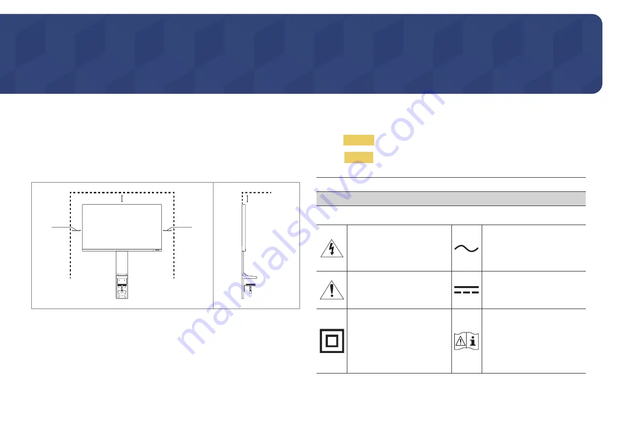
Securing the Installation Space

Make sure to have enough space for ventilation when placing the product. An internal temperature rise 
may cause fire and damage the product. Maintain enough space around the product as shown in the 
diagram when installing the product.


The exterior may differ depending on the product.

10 cm (3.93 Inches)

10 cm (3.93 Inches)

10 cm

(3.93 Inches)

10 cm

(3.93 Inches)

Safety Precautions

Warning

A serious or fatal injury may result if instructions are not followed.

Caution

Personal injury or damage to properties may result if instructions are 
not followed.

CAUTION

RISK OF ELECTRIC SHOCK. DO NOT OPEN.

CAUTION: TO REDUCE THE RISK OF ELECTRIC SHOCK, DO NOT REMOVE COVER (OR BACK). THERE 
ARE NO USER SERVICEABLE PARTS INSIDE. REFER ALL SERVICING TO QUALIFIED PERSONNEL.

This symbol indicates that high 
voltage is present inside. It is 
dangerous to make any kind of 
contact with any internal part of this 
product.

AC voltage: Rated voltage marked 
with this symbol is AC voltage.

This symbol indicates that this 
product has included important 
literature concerning operation and 
maintenance.

DC voltage: Rated voltage marked 
with this symbol is DC voltage.

Class II product: This symbol indicates 
that a safety connection to electrical 
earth (ground) is not required. If this 
symbol is not present on a product 
with a mains lead, the product 
MUST have a reliable connection to 
protective earth (ground).

Caution. Consult instructions for use: 
This symbol instructs the user to 
consult the user manual for further 
safety related information.

Before Using the Product

Chapter  01

Summary of Contents for S27R754Q

Page 1: ...contents of this manual are subject to change without notice to improve quality Samsung Electronics Samsung Electronics owns the copyright for this manual Use or reproduction of this manual in parts o...

Page 2: ...Stand 22 Tidying Up the Connected Cables 23 Connecting and Using a Source Device Read below before installing the product 24 Connecting and Using a PC 24 Connection Using the HDMI Cable 24 Connection...

Page 3: ...d Problems with the Installation 41 Upgrade by downloading the firmware from the website 41 System Requirements 41 Troubleshooting Guide Requirements Before Contacting Samsung Customer Service Center...

Page 4: ...OR BACK THERE ARE NO USER SERVICEABLE PARTS INSIDE REFER ALL SERVICING TO QUALIFIED PERSONNEL This symbol indicates that high voltage is present inside It is dangerous to make any kind of contact wit...

Page 5: ...h to wipe the exterior of the product clean 5 Connect the power cord to the product when cleaning is finished 6 Power on the product and PC Electricity and Safety Warning Do not use a damaged power co...

Page 6: ...en Edible oil such as soybean oil may damage or distort the product Keep the product away from oil pollution And do not install or use the product in the kitchen or near the kitchen stove Caution Do n...

Page 7: ...m power off the product and remove the power cable Do not drop objects on the product or apply impact Do not move the product by pulling the power cord or any cable If a gas leakage is found do not to...

Page 8: ...sult Keep the AC DC adapter in a well ventilated area If you place the AC DC power adapter hanging with the cord input facing upwards water or other foreign substances could enter the Adapter and caus...

Page 9: ...ook at distance objects for every1 hour of product use Do not touch the screen when the product has been turned on for an extended period of time as it will become hot Store small accessories out of t...

Page 10: ...indicator and works as Power On Power button Power LED Off Power saving mode Power LED Blinking Power Off Power button Power LED On The Power LED operation can be swapped by changing in the menu Syste...

Page 11: ...e screen the following menu options appearwhen the product screen is switched on or the input source is changed Eye Saver Mode Features Eye Saver ModeOff UP DOWN Adjust Brightness Contrast Eye SaverMo...

Page 12: ...t other users from changing settings Enable Disable To enable or disable the on screen display menu lock display the Menu screen move the jog button to the right to go to the next stage and then press...

Page 13: ...uring Eye Saver Mode Brightness and Contrast from Direct Key Guide Adjust the Brightness Contrast and Eye SaverMode by moving the JOG button Eye Saver Mode Brightness Contrast Off The displayed image...

Page 14: ...C 19V SERVICE MINI DP IN HDMI IN Port Description SERVICE Use a USB memory stick to perform software upgrade MINI DP IN MINI DPIN Connects to a PC using a MINI DP cable S27R75 MINI DP IN support 2560...

Page 15: ...for approximately 5 seconds Power Off 2 When the message as shown in the following figure is displayed on the product select Yes to upgrade the software Yes No Do you want to update via USB 3 When the...

Page 16: ...ventions for the SR75 32 model and should be copied to the root directory 4 If the No valid update files found Please check yourUSB device and try again message is displayed this is probably due to th...

Page 17: ...tore the product with the screen facing down It is recommended that the product be tilted to an angle within the optimum range When installing the product close to a wall with excessive force exercise...

Page 18: ...ng the product Do not directly apply pressure on the screen Do not hold the screen when moving the product Do not hold the product upside down only by the stand Hold the lower corners or edges of the...

Page 19: ...hen lowering the product close to the floor make sure you hold the sides of the product Do not lower the product with excessive force There is a risk of damage to your hands Do not put any object unde...

Page 20: ...before installing the stand on the table It is difficult to tidy up cables if the gap between the table and the partition is narrow For details on how to tidy up cables refer to Tidying Up the Connect...

Page 21: ...on on the table to protect the product screen 1 3 4 Make sure the product front faces down as shown in the figure Attach and fix the stand to the rear of the product by using the screws Attach the Cov...

Page 22: ...risk of damaging the product Before placing the product facing down to the table put a cushion on the table to protect the product screen 1 2 3 4 Turn the clamp on the stand installed on the table to...

Page 23: ...as shown in the figure 2 Tidy up the connected Y cable by aligning it with the stand groove as shown in the figure Make sure the Y cable is tidied up at the left of the groove The MINI DP cable can be...

Page 24: ...information required to use the product properly Connecting and Using a PC Select a connection method suitable foryour PC Connecting parts may differ in different products Provided ports may vary depe...

Page 25: ...that the graphics card of the MINI DP source supports 3840 x 2160 60 Hz Connecting the Power 2 5 4 3 1 1 Connect the power plug to the AC DC adapter Do not remove the power plug after assembly 2 Conn...

Page 26: ...r blink frequently then eye fatigue will be relieved Driver Installation You can set the optimum resolution and frequency for this product by installing the corresponding drivers To install the latest...

Page 27: ...and brightness as required Standard Obtain a picture quality suitable for editing documents or using Internet Cinema Obtain the brightness and sharpness of TVs suitable for enjoying video and DVD con...

Page 28: ...e when PIP PBP Mode is set to On Color Adjust the tint of the screen This menu is not available when SAMSUNG MAGICBright is set to Cinema or Dynamic Contrast mode This menu is not available when Game...

Page 29: ...e Set to an optimum picture quality suitable for eye relaxation T V Rheinland Low Blue Light Content is a certification for products which meet requirements for lower blue light levels When Eye SaverM...

Page 30: ...ts provided with the product Changing the Picture Size is available when the following conditions are satisfied The input source is 480p 576p 720p or1080p and product can display normally Not every mo...

Page 31: ...fly or appear after a delay when you enable or disable the PIP PBP function or when you change the screen size with the PIP PBP function activated This can typically arise when a PC and a product are...

Page 32: ...nput source In AV mode 4 3 Display the picture of the sub screen with an aspect ratio of 4 3 Suitable forvideos and standard broadcasts 16 9 Display the picture of the sub screen with an aspect ratio...

Page 33: ...Display the picture of the sub screen with the original aspect ratio without cutting anything off The function may not be supported depending on the ports provided with the product Changing the scree...

Page 34: ...ce to improve quality Transparency Set the transparency for the menu windows Position H Position Move the menu position to the left or right V Position Move the menu position up or down Language Set t...

Page 35: ...t to change without notice to improve quality Self Diagnosis 1 Use the Function Key Guide and go to System Self Diagnosis Self Diagnosis DisplayPort Ver HDMI Mode Eco Saving Plus Off Timer Plus PC AV...

Page 36: ...nother port of your PC or connected device Reset the settings in System Reset All It is recommended that you use the cable provided at purchase OK DisplayPort Ver Select the DisplayPort version to use...

Page 37: ...frequency from the graphics card The response rate during the game may fluctuate depending on the resolution A higher resolution generally decreases the response rate The sound quality of the monitor...

Page 38: ...gy compared to the maximum brightness Off Timer Plus Configuring Off Timer Off Timer Turn on Off Timer mode Turn Off After The off timer can be set within a range of 1 to 23 hours The product will aut...

Page 39: ...DMI DisplayPort PC or AV Source Detection Select either Auto or Manual as the method to recognize input source Not available when PIP PBP Mode is set to On Key Repeat Time Control the response rate of...

Page 40: ...ve quality Information View the current input source mode frequency and resolution that are in use and the current product version Information Picture PIP PBP OnScreen Display System Information Infor...

Page 41: ...cut icon does not appear press the F5 key Restrictions and Problems with the Installation The Easy Setting Box installation may be affected by the Graphics Card Motherboard and the Networking Environm...

Page 42: ...ion between the product and PC and ensure the connectors are locked Blank spaces are found on all four sides of the screen when an HDMI cable is connected to the product and PC The blank spaces found...

Page 43: ...ithin the range of resolution and frequency compatible with the product Next if required change the settings referring to Standard Signal Mode Table P 46 in this manual and the Information menu on the...

Page 44: ...n refresh rate under Monitorsettings How can I change the resolution Windows 7 Go to Control Panel Appearance and Personalization Display Screen Resolution Adjust Resolution Windows 8 Windows 8 1 Go t...

Page 45: ...e 4 F 113 F 20 C 45 C Humidity 5 95 non condensing Plug and Play This product can be installed and used with any Plug and Play compatible systems Two way data exchange between the product and PC syste...

Page 46: ...ings according to the following table by referring to the graphics card user manual DisplayPort S27R75 Resolution Horizontal Frequency kHz Vertical Frequency Hz Pixel Clock MHz Sync Polarity H V IBM 7...

Page 47: ...919 99 946 410 500 VESA CVT 2560 x1440 182 996 119 998 497 750 VESA CVT 2560 x1440 222 192 144 000 586 586 HDMI S27R75 Resolution Horizontal Frequency kHz Vertical Frequency Hz Pixel Clock MHz Sync Po...

Page 48: ...680 x1050 65 290 59 954 146 250 VESA DMT 1920 x1080 67 500 60 00 148 500 VESA CVT 2560 x1440 88 787 59 951 241 500 VESA CVT 2560 x1440 150 919 99 946 410 500 VESA CVT 2560 x1440 182 996 119 998 497 75...

Page 49: ...75 025 135 000 VESA 1440 x 900 55 935 59 887 106 500 VESA 1600 x 900 60 000 60 000 108 000 VESA 1680 x1050 65 290 59 954 146 250 VESA 1920 x1080 67 500 60 000 148 500 VESA 2560 x1440 88 787 59 951 241...

Page 50: ...60 000 594 000 Horizontal Frequency The time required to scan a single line from the left to the right side of the screen is called a horizontal cycle The reciprocal number of a horizontal cycle is c...

Page 51: ...ogram If customer requests software installation and setup for the product If a service technician removes cleans dusts or foreign materials inside of the product If customer requests an installation...

Reviews: