background image

17

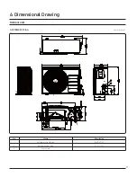
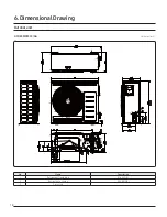
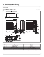
6. Dimensional Drawing

AC018MXSCCC/AA

Unit: mm (inch)

Ęͱࢋ

Name

Uʪϑʀθ̈Χϩ̈ͱ͝

1

Refrigerant liquid pipe

עߧࢋߤߦ࣍ߢࢥߥ࣎

2

Refrigerant gas pipe

עߢߣࢋߨ࣍ߢࢥߣ࣎

3

Drain Hole

-

Outdoor unit

Summary of Contents for RAC Series

Page 1: ...A UA A AAA SINGLE RAC forAmerica LowAmbient R410A Cooling Only System SINGLE Technical Data Book...

Page 2: ...2 History U Ver 1 0 Release Single RAC TDB for America Low Ambient R410A CO 17 05 05 Ver 1 Re 9 U k 1 0 0...

Page 3: ...tion 1 1 Way Cassette 4 Way Cassette 600x600 4 4 Way Cassette 360 Cassette L LSP Duct M MSP Duct C Ceiling J Console A A3050 Wall Mounted T RAC 6 Feature F Flagship Standard U Deluxe P Premium C Delux...

Page 4: ...Product Type Indoor Unit Outdoor Unit 5 Product Notation A Inv Side General Temp Inv Side Low Temp 6 Feature F Flagship Standard U Deluxe P Premium C Deluxe Low Temp 7 Rating Voltage C 1 208 230V 60H...

Page 5: ...5 Contents A A A U U A k U U U...

Page 6: ...1 Line up 6 1 1 IndoorUnits Model A 9 18 24 RAC 1 2 Outdoorunits Model A 9 18 24...

Page 7: ...A A mm 0 75 0 75 0 75 0 75 F1 F2 F1 F2 F1 F2 F1 F2 R410A R410A R410A R410A A EEV EEV EEV EEV A 1 30 2 00 2 40 2 40 2 87 4 41 5 29 5 29 1 2 208 230 60 1 2 208 230 60 1 2 208 230 60 1 2 208 230 60 k Fin...

Page 8: ...3 40 3 x 35 9 x16 3 39 2 x 43 1 x16 8 A 9 EGI Steel Plate EGI Steel Plate EGI Steel Plate EGI Steel Plate A 5 23 46 115 5 23 46 115 5 23 46 115 5 23 46 115 40 40 46 115 40 40 46 115 40 40 46 115 40 40...

Page 9: ...35 AC030MNTDCH AA 40 57 Max 37 000 High 777 49 Std 30 000 Mid 724 47 Min 9 000 Low 671 45 AC036MNTDCH AA 40 57 Max 38 000 High 830 51 Std 36 000 Mid 752 48 Min 10 000 Low 699 46 OutdoorUnit A 9 Model...

Page 10: ...AC024MXSCCC AA 60 208 to 230 187 253 10 5 0 9 0 7 16 16 20 AC030MNTDCH AA AC030MXSCCC AA 60 208 to 230 187 253 16 5 1 51 0 9 24 24 30 AC036MNTDCH AA AC036MXSCCC AA 60 208 to 230 187 253 16 5 1 51 0 9...

Page 11: ...2 0 15 3 2 93 22 4 15 1 2 96 23 6 15 0 2 99 24 7 14 7 3 05 3 AC030MNTDCH AA AC030MXSCCC AA TC Total Capacity SHC Sensible Heat Capacity PI Power Input Outdoor Temperature U9 U9 9 TC SHC PI TC SHC PI T...

Page 12: ...AA U 0 97 0 97 0 96 0 96 0 95 0 98 0 97 0 97 0 96 0 96 0 95 0 98 0 98 0 97 0 97 0 96 0 96 0 95 0 99 0 98 0 98 0 97 0 97 0 96 0 96 0 95 0 99 0 99 0 98 0 98 0 97 0 97 0 96 0 96 0 95 1 00 0 99 0 99 0 98...

Page 13: ...98 0 97 0 97 0 96 0 96 0 90 0 99 0 99 0 98 0 98 0 97 0 97 0 96 0 96 0 90 1 00 0 99 0 99 0 98 0 98 0 97 0 97 0 96 0 96 0 90 0 1 00 0 99 0 99 0 98 0 98 0 97 0 97 0 96 0 96 0 90 1 00 0 99 0 99 0 98 0 98...

Page 14: ...mensional Drawing AC018MNADCH AA Unit mm inch Name U 1 Liquid pipe connection 6 35 1 4 2 Gas pipe connection 12 7 1 2 3 Drain pipe connection ID 18 HOSE 4 Power supply Communication wiring conduit Ind...

Page 15: ...16 3 1 4 3 13 16 11 1 4 11 1 4 11 7 8 6 6 5 8 1 5 16 15 16 4 5 16 3 5 16 22 7 16 6 5 8 3 5 16 4 5 16 1 5 16 2 1 2 5 3 16 2 7 16 Name U 1 Liquid pipe connection 6 35 1 4 2 Gas pipe connection 15 88 5 8...

Page 16: ...3 16 1280 13 9 16 1530 50 3 8 364 60 1 4 382 14 5 16 156 15 1 16 6 1 8 1 3 8 34 125 67 2 5 8 4 15 16 2 9 16 Wall hole for right rear piping Wall hole for right rear piping 2 9 16 64 2 9 16 34 1 3 8 Na...

Page 17: ...17 6 Dimensional Drawing AC018MXSCCC AA Unit mm inch Name U 1 Refrigerant liquid pipe 2 Refrigerant gas pipe 3 Drain Hole Outdoorunit...

Page 18: ...6 Dimensional Drawing 18 Outdoorunit AC024MXSCCC AA Unit mm inch Name U 1 Refrigerant liquid pipe 2 Refrigerant gas pipe 3 Drain Hole...

Page 19: ...nsional Drawing Outdoorunit AC030MXSCCC AA AC036MXSCCC AA Unit mm inch Name U 1 Refrigerant gas pipe 2 Refrigerant liquid pipe 3 Drain Hole Connect with the provided drain plug 4 Communication wiring...

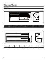
Page 20: ...doorUnit Unit mm inch A B C D E F A 9 C U E F AC018MNADCH AA AC024MNADCH AA Unit mm inch A B C D E F G A 9 C U E F F AC030MNTDCH AA AC036MNTDCH AA 1280 50 3 8 412 16 1 4 207 8 1 8 345 13 9 16 253 9 15...

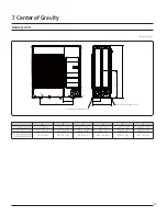
Page 21: ...21 7 Centerof Gravity OutdoorUnit Unit mm inch Hold location of foundation bolt Hold location of foundation bolt C D A F B E A 9 C U E F AC018MXSCCC AA AC024MXSCCC AA AC030MXSCCC AA AC036MXSCCC AA...

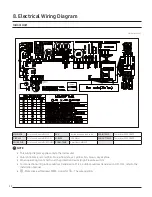
Page 22: ...WIRE SUB Print circuit board SUB COMM ROOM TEMP Thermistor AMBIENT NOTE This wiring diagram applies only to the indoor unit Colors blk black red red blu blue wht white yel yellow brn brown sky skyblue...

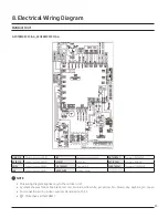
Page 23: ...UT TH 10K ThermistorAMBIENT SMPS Printed circuit board SMPS OLT TH 200K Thermistor OLP COND TH 10K Thermistor CONDENSOR SUB Printed circuit board SUB BELTHEATER Comp Belt Heater NOTE This wiring diagr...

Page 24: ...board INVERTER M BLDC BLDC Motor OUT TH 10K ThermistorAMBIENT EMI Printed circuit board EMI OLT TH 200K Thermistor OLP COND TH 10K Thermistor CONDENSOR BELTHEATER Comp Belt Heater NOTE This wiring dia...

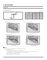
Page 25: ...Octave Band Center Frequency Hz 3 AC030MNTDCH AA 4 AC036MNTDCH AA High Low NC 50 NC 70 NC 60 NC 55 NC 45 NC 40 NC 35 NC 30 NC 25 NC 20 NC 15 0 5 10 15 20 25 30 35 40 45 50 55 60 65 70 0 5 10 15 20 25...

Page 26: ...d Center Frequency Hz 3 AC030MXSCCC AA 4 AC036MXSCCC AA Hearing threshold Cooling NC 50 NC 70 NC 60 NC 55 NC 45 NC 40 NC 35 NC 30 NC 25 NC 20 NC 15 0 5 10 15 20 25 30 35 40 45 50 55 60 65 70 75 80 85...

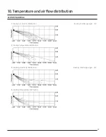
Page 27: ...7 10 Temperature and airflow distribution AC018MNADCHAA 1 Cooling airvelocity distribution A U 2 Cooling Temperature distribution 3 Heating airvelocity distribution U 4 Heating Temperature distributio...

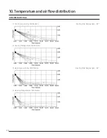
Page 28: ...0 Temperature and airflow distribution 28 AC024MNADCHAA 1 Cooling airvelocity distribution A U 2 Cooling Temperature distribution 3 Heating airvelocity distribution U 4 Heating Temperature distributio...

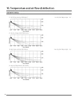
Page 29: ...9 10 Temperature and airflow distribution AC030MNTDCHAA 1 Cooling airvelocity distribution A U 2 Cooling Temperature distribution 3 Heating airvelocity distribution U 4 Heating Temperature distributio...

Page 30: ...0 Temperature and airflow distribution 30 AC036MNTDCHAA 1 Cooling airvelocity distribution A U 2 Cooling Temperature distribution 3 Heating airvelocity distribution U 4 Heating Temperature distributio...

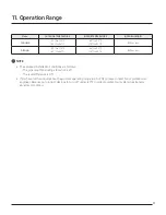
Page 31: ...ING 80 or less NOTE The assumed installation conditions are follows The pipe length including elbow is 24 6 ft The level difference is 0 ft If you have further inquiry about beyond our operating range...

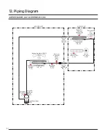
Page 32: ...eat Exchanger IN T_II Heat Exchanger Indoor unit HX_ID INDOOR UNIT OUTDOOR UNIT Thermistor Indoor Room T_IR Indoor Fan Motor IFM Electronic Expansion Valve Main E_M Thermistor Discharge pipe T_D Crank...

Page 33: ...T_II Heat Exchanger Indoor unit HX_ID INDOOR UNIT OUTDOOR UNIT Thermistor Indoor Room T_IR Indoor Fan Motor IFM Electronic Expansion Valve Main E_M Thermistor Discharge pipe T_D CrankCaseHeater CCH Th...

Page 34: ...d Drain hose hole You can select the direction of draining left orright Maximum pipe height 26 25 ft 8 m Maximum pipe length 49 21 ft 15 m Make at least one round to reduce noise and vibration The act...

Page 35: ...distances between the hole and the installation plate Left Right Rearright orleft Bottom right CAUTION If changing the pipe direction from left to right do not drastically bent it but slowly turn it i...

Page 36: ...not be lighterthan polychloroprene sheathed flexible cord Code designation IEC 60245 IEC 66 CENELEC H07RN F IEC 60245 IEC 57 CENELEC H05RN F Power Communication cable shall not exceed 98 42 ft 30m CAU...

Page 37: ...and serviceable Fixing the installation plate You can install the indoor unit on a wall window frame or gypsum board WARNING Make sure that the wall window frame or gypsum board can withstand the wei...

Page 38: ...ssary noise and vibration Position the outdoor unit so that the airflow is directed towards the open area Maintain sufficient clearance around the outdoor unit especially from a radio computer stereo...

Page 39: ...pport wall or ground Fix the outdoor unit with anchor bolts NOTE The anchor bolt must be 0 79 inch or higherfrom the base surface Anchor bolt hole Unit inch 11 22 12 48 13 50 24 09 31 10 Unit inch Anc...

Page 40: ...The connection cord between indoor unit and outdoor unit The power cable between outdoor unit and auxiliary circuit breaker Be sure to run the power supply cable and the communication cable through e...

Page 41: ...talling the indoor unit in a computer room or net work room use the double shielded Tape aluminum polyester braid copper cable of FROHH2R type 1 phase terminal block spec A A 1 L 2 N N L 0 59 0 47 0 4...

Page 42: ...ain supply connection is made through a switch that disconnects all poles with contact gap of a least 0 12 in Devices disconnected from the power supply should be completely disconnected in the condit...

Page 43: ...9 16 50 2 8 4 1 3 16 0 4 0 015 0 0 1 8 0 07 70 0 10 8 3 16 24 1 0 4 0 015 17 5 11 16 0 5 0 019 0 4 0 015 13 3 1 2 0 4 0 015 18 5 3 4 20 3 4 51 2 8 4 1 3 16 0 4 0 015 0 0 2 0 0 078 Connect the rated ca...

Page 44: ...rless 98 4 ft 30 m orless A AC030 036MXSCCC 164 0 ft 50 m 98 4 ft 30 m indoor outdoor L1 h1 Temper grade and minimum thickness of the refrigerant pipe 1 4 0 0276 C1220T O 3 8 0 0276 1 2 0 0315 5 8 0 0...

Page 45: ...ly be A 1 Check that the stop valve is closed entirely 2 Charge the refrigerant through the service port of liquid stop valve NOTE Do not charge the refrigerant through the gas side service port 3 If...

Page 46: ...the liquid pipe Determine the liquid pipe length before adding refrigerant This operation can only be performed by a qualified refrigeration specialist Single installation outdoorunit AC018MXSCCC 0 1...

Page 47: ...8UN MIM B18BUN A A On Off Controller MCM A202DN Touch Controller MCM A300N Wi Fi Kit MIM H03UN A Wireless remote Controller MR EH00U Except for 360 Cassette AR KH00U 360 Cassette Only Wired remote Con...

Page 48: ...sensor MRW TA Compatible interface module MIM N01 External contact interface module MIM B14 S Converter MIM C02N In case you want more information about the accessories please refer to the control an...

Page 49: ...Office Suwon Korea 129 Samsung Ro Yeongtong Gu Suwon City Gyeonggi Do Korea 16677 Website www samsung com http btsp samsunggsbn com Email airconditioner samsung com Images and data in this book may su...

Reviews: