background image

5

OM55N-D

Air inlet

Air outlet


"

The color and shape of parts may differ from what is shown. Specifications are subject to change without notice 

to improve quality.


"

Install this product for indoors only. Install the display labeled 

OUTDOOR

 in the direction of the window.

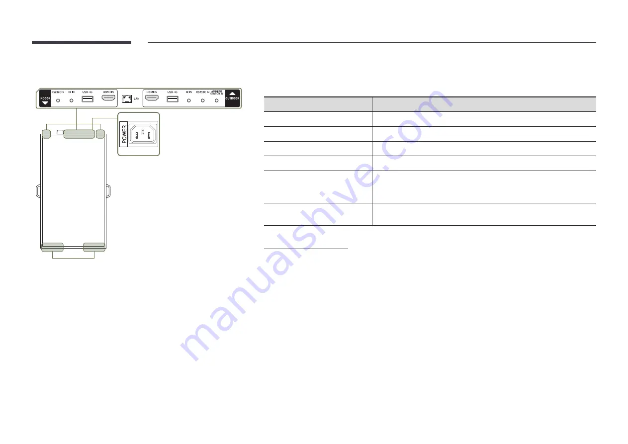
Port

Description

RS232C IN

Connects to MDC using an RS232C adapter.

IR IN

Connects to an external IR cable that receives signals from the remote control.

USB 

¨

Connect to a USB memory device.

HDMI IN

Connects to a source device using a HDMI cable or HDMI-DVI cable.

LAN


Wired LAN connection port used to connect an external device such as a 

laptop to connect to the Internet.


• Connects to MDC using a LAN cable. (10/100 Mbps)

AMBIENT SENSOR IN 

Used to supply power to the external sensor board and to receive signals from 
the ambient light sensor.

Setting up Device ID

OM55N-D

 model has separate remote sensors on the front and back sides.

Depending on the distance from the remote control or other surrounding conditions, it is possible both front and 

back displays respond to the remote control signal. You can assign IDs to displays (INDOOR: 1, OUTDOOR: 2) and 

follow the steps below to restrict remote control to one selected display only.


"

To reverse the remote controlled display after setting otherwise, first cancel the existing ID settings for the 

INDOOR and OUTDOOR displays by pressing the 

UNSET

 button.


To select the INDOOR display only

1) Position the remote control facing the INDOOR IR sensor and press 

SET

 → 

1

 → 

E

 on the control.

2)

 Position the remote control facing the OUTDOOR IR sensor and press 

SET

 → 

1

 → 

E

 on the control.


• To select the OUTDOOR display only

1) Position the remote control facing the INDOOR IR sensor and press 

SET

 → 

2

 → 

E

 on the control.

2)

 Position the remote control facing the OUTDOOR IR sensor and press 

SET

 → 

2

 → 

E

 on the control.

Summary of Contents for OMN Series

Page 1: ...right forthis manual Use orreproduction of this manual in parts orentiretywithout the authorization of Samsung Electronics is prohibited Trademarks otherthan Samsung Electronics are property of theirrespective owners OMN OM46N OM55N OMN D OM55N D The color and the appearance may differ depending on the product and the content in the manual is subject to change without prior notice to improve the p...

Page 2: ...55N 4 OM55N D 5 Anti theft Lock 6 Before Installing the Product Installation Guide 7 OM46N OM55N 7 OM55N D 8 Installing the Wall Mount 11 Installing the Wall Mount 11 Wall Mount Kit Specifications VESA 11 Specifications General 12 Preset Timing Modes 13 Appendix License 15 2 ...

Page 3: ...ambient light sensor The warrantyforadhesiveness of the double sided tape applies to first time use only The external ambient light sensoris marked with the label on the sensor cable Checking the Components Quick Setup Guide Warranty card Not available in some locations Regulatory guide Power cord Batteries AAA x 2 Not available in some locations Remote Control External ambient light sensor Extern...

Page 4: ...ts sound to an audio device via an audio cable IR IN Connects to an external IR cable that receives signals from the remote control AMBIENTSENSOR IN Used to supply power to the external sensor board and to receive signals from the ambient light sensor USB Connect to a USB memory device LAN OUT Wired LAN connection port used to connect an external device such as a laptop to connect to the Internet ...

Page 5: ...ensor Setting up Device ID OM55N D model has separate remote sensors on the front and back sides Depending on the distance from the remote control or other surrounding conditions it is possible both front and back displays respond to the remote control signal You can assign IDs to displays INDOOR 1 OUTDOOR 2 and follow the steps below to restrict remote control to one selected display only To reve...

Page 6: ... the images Supported models OM46N OM55N To lock an anti theft locking device 1 Fix the cable of your anti theft locking device to a heavy object such as a desk 2 Put one end of the cable through the loop on the other end 3 Insert the locking device into the anti theft lock slot at the back of the product 4 Lock the locking device An anti theft locking device can be purchased separately Refer to t...

Page 7: ...d Rotation Contact Samsung Customer Service Center for further details The product can be tilted at a maximum angle of 15 from a perpendicularwall surface 15 Do not use this model installed on a ceiling floor or table Ventilation Contact Samsung Customer Service Center for further details Installation on a PerpendicularWall A Minimum 60 mm B Ambient temperature Under 30 C When installing the produ...

Page 8: ... stations Oil mist may cause fans to malfunction Do not use in Landscape mode for this model Ventilation Do not block the ventilation openings on the top and bottom sides A Distance from the show window 100 mm B Distance from the ceiling 300 mm C Distance from the floor 100 mm D Operation temperature range 0 30 under direct sunlight C B A D ...

Page 9: ... into the power IN rubber and connect the power cord Connect cables e g external IR cable power cord HDMI cable and organize them as shown in the image Place the top cover Securely position the external IR cable and the external ambient light sensor at the specified location ...

Page 10: ...ions before installing on the ceiling orwith the stand Precautions forenclosure unit installation If you want to make additional enclosure surrounding OMN D product refer to the following guides There should be no glass in front and back of the Enclosure Don t block the top and bottom vents of OMN D product Open rate above 70 is recommended for Inlet Outlet vent of Enclosure ...

Page 11: ...ided Do not use screws that are longer than the standard length or do not comply with the VESA standard screw specifications Screws that are too long may cause damage to the inside of the product Forwall mounts that do not comply with the VESA standard screw specifications the length of the screws may differ depending on the wall mount specifications Do not fasten the screws too firmly This may da...

Page 12: ...ay This monitor can be installed and used with any Plug and Play compatible systems Two way data exchange between the monitor and PC system optimizes the monitor settings Monitor installation takes place automatically However you can customize the installation settings if desired Due to the nature of the manufacturing of this product approximately1 pixel per million 1ppm may appear brighter or dar...

Page 13: ...l Frequency 24 75 Hz HDMI 30 75 Hz DisplayPort 24 75 Hz HDMI Resolution Optimum resolution 1920 x 1080 60 Hz Maximum resolution 3840 x 2160 60 Hz Horizontal Frequency The time required to scan a single line from the left to the right side of the screen is called a horizontal cycle The reciprocal numberof a horizontal cycle is called horizontal frequency Horizontal frequency is measured in kHz Vert...

Page 14: ... 31 500 VESA 800 x 600 35 156 56 250 36 000 VESA 800 x 600 37 879 60 317 40 000 VESA 800 x 600 48 077 72 188 50 000 VESA 800 x 600 46 875 75 000 49 500 VESA 1024 x 768 48 363 60 004 65 000 VESA 1024 x 768 56 476 70 069 75 000 VESA 1024 x 768 60 023 75 029 78 750 VESA 1152 x 864 67 500 75 000 108 000 Resolution Horizontal Frequency kHz Vertical Frequency Hz Pixel Clock MHz Sync Polarity H V VESA 12...

Page 15: ...nce Notice contact the Samsung Customer Center or send email to oss request samsung com THIS PRODUCT IS SOLD WITH A LIMITED LICENCE AND IS AUTHORISED TO BE USED ONLY IN CONNECTION WITH HEVC CONTENT THAT MEETS EACH OF THE THREE FOLLOWING QUALIFICATIONS 1 HEVC CONTENT ONLY FOR PERSONAL USE 2 HEVC CONTENT THAT IS NOT OFFERED FOR SALE AND 3 HEVC CONTENT THAT IS CREATED BY THE OWNER OF THE PRODUCT THIS...

Reviews: