


CHAPTER 2.
Ошибка! Используйте вкладку "Главная" для применения
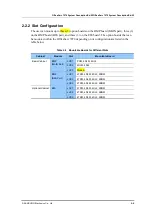
제목
1 к тексту, который должен здесь
отображаться.
2-14
© SAMSUNG Electronics Co., Ltd.
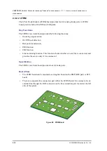
Board View
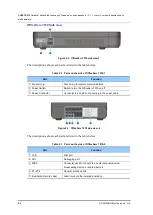
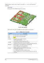
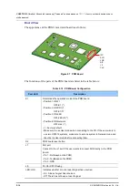
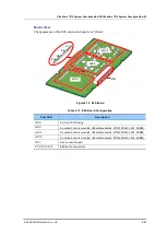
The appearance of the PRM voice trunk board is as follows:
Figure 2.7 PRM Board
The functions of the parts of the PRM board are listed in the table below:
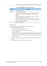
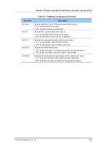
Table 2.10 PRM Board Configuration
Port, LED
Description
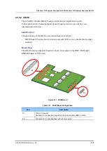
S1
Determines the operation mode of the PRM board.
- Position1: ON-T1
OFF-E1 (*)
- Position2: ON-PRI (*)
OFF-E1/T1
- Position3: ON-24B
OFF-24B+D (*)
- Position4: ON-Network
OFF-User (*)
- (*): Factory default.
- Make sure to use User mode when connecting to the CO. If the user wants to
use two OS7070 systems, make sure to set one system to Network mode and
the other to User mode before connecting them.
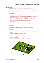
S2
PRM board reset button
J1
SIO port
Connect to the J1 port if the user wants to connect SIO directly to the PRM
board.
- Pin 1: Rx (Based on the PRM)
- Pin 2: Tx (Based on the PRM)
- Pin 3: GND
J5
Port for CPLD fusing
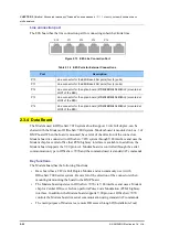
LED: LOS
Indicates whether or not a loss of signal has occurred.
- On: A loss of signal has occurred.
- Off: There has not been a loss of signal.
IPC
SYN
LOS
AIS
L2
CLK
S2
J5
S1
J1


