


- Satellite Broadcasting
Broadcasting service provided via satellite.
Enables high picture quality and clear sound
throughout the country regardless of the location of
the viewer.
- Sound Balance
Balances the levels of the sound coming from
each speaker in televisions with two speakers.
- Cable TV
Whereas the terrestrial broadcasting is delivered
via frequency signals through the air, cable broad-
casting is transmitted via a cable network. In order
to view cable TV, one must purchase a cable
receiver and hook it up to the cable network.
- CATV
"CATV" refers to the broadcasting service offered
at hotels, schools and other buildings through their
own broadcasting system, apart from VHF or UHF
broadcasting by terrestrial broadcasters. The
CATV programs may include movies, entertain-
ment and educational programs. (Different from
cable TV.)
CATV can be viewed only within the area in which
the CATV service is offered.
- S-Video
Short for "Super Video." S-Video allows up to 800
lines of horizontal resolution, enabling high-quality
video.
- VHF/UHF
VHF indicates TV channels 2 to 13, and UHF indi-
cates channels 14 through 69.
- Channel Fine Tuning
This feature allows the viewer to fine-tune the TV
channel to obtain the best viewing conditions. The
Samsung LCD TV has both automatic and manual
channel fine-tuning features to enable the viewer
to adjust their desired settings.
- External Device Input
External device input refers to video input from
such external video devices as VCRs, camcorders
and DVD players, separate from a TV broadcast.
14 Reference Infomation
14-3
Summary of Contents for LE40M91B
Page 3: ...Contents ...
Page 4: ...Contents ...
Page 27: ...4 Troubleshooting 4 4 WAVEFORMS 1 R G B Output Signal of IC500 ...
Page 29: ...4 Troubleshooting 4 6 2 Digital Output Data of IC500 3 Signal of HDMI Data ...
Page 31: ...4 Troubleshooting 4 8 WAVEFORMS 4 Tuner_CVBS Output Signal 3 CVBS Output Signal ...
Page 33: ...4 Troubleshooting 4 10 WAVEFORMS 4 CVBS Output Signal ...
Page 35: ...4 Troubleshooting 4 12 2 Digital Output Data of IC500 5 Analog Signal Y C to IC500 WAVEFORMS ...
Page 37: ...4 Troubleshooting 4 14 WAVEFORMS 6 The Signal are Inputed to IC1015 7 DC 12V ...
Page 69: ...8 1 8 Wiring Diagrams 8 Wiring Diagram 8 1 LE40M91BX Wiring Diagram ...
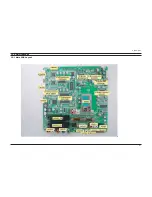
Page 70: ...8 Wiring Diagrams 8 2 8 2 Main Board Layout ...
Page 74: ...8 Wiring Diagrams 8 6 8 4 Power Board Layout ...
Page 77: ...8 9 8 Wiring Diagrams ...
Page 81: ...9 Schematic Diagrams 9 2 9 2 Input Output Schematic Diagram ...
Page 82: ...9 Schematic Diagrams 9 3 9 3 Input Output Schematic Diagram ...
Page 83: ...9 Schematic Diagrams 9 4 9 4 Micom Schematic Diagram ...
Page 84: ...9 Schematic Diagrams 9 5 9 5 SVP PX Schematic Diagram ...
Page 85: ...9 Schematic Diagrams 9 6 9 6 Application Schematic Diagram ...
Page 86: ...9 Schematic Diagrams 9 7 9 7 FRCH 100Hz LVDS Schematic Diagram ...
Page 87: ...9 Schematic Diagrams 9 8 Memo ...
Page 98: ...12 PCB Diagram 12 1 12 PCB Diagram 12 1 Main PCB Layout ...