background image

24 _ Disassembly and Reassembly 

Part

figure

Description

DOOR REVERSAL
(Continued)

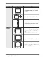
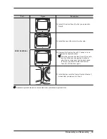
11. Turn the Holder-Glass upside down and remove 

the 8 screws.

12. Remove 2 Support-Hinges and the Hinge-Door.

13. Remove the screw, insert the removed screw into 

the bottom hole, and then fasten it.

14. Assemble the Support-Hinge and the Hinges that 

you removed in Step 12, as shown by the figure 

below.

15. Fasten the 8 screws that you removed in Step 11.

16. Install 2 Guide-Holder Glasses onto the other side.

17. Assemble the Holder-Glass by sliding it so that the 

upper hook is caught and fasten the 15 screws that 

you removed in Step 9.

Summary of Contents for DV448AEP

Page 1: ...d Specifications 3 Disassembly and Reassembly 4 Troubleshooting 5 Exploded views and Parts list 6 PBA diagram 7 Wiring diagram 8 Schematic diagram Basic Model DV448AEP XAA Model Name DV5471AEP DV5471AGP DV5471AEW DV5471AGW DV5451AEW DV5451AGW ORCA DRYER PROJECT Model Code DV5471AEP XAA DV5471AGP XAA DV5471AEW XAA DV5471AGW XAA DV5451AEW XAA DV5451AGW XAA DV5471A DV5451A ...

Page 2: ...ons 31 4 5 Component testing procedures 36 5 Exploded views and Parts list 39 5 1 MAIN 40 5 2 Ass y Frame Front Door 48 5 3 Ass y Panel Control 62 5 4 Ass y Drum Parts 70 5 5 Ass y Motor 84 5 6 Ass y Duct Heater 92 5 7 Ass y Duct Burner 96 5 8 Small Parts 100 5 9 PARTS LIST SA SC OTHER 106 5 10 PARTS LIST SCREW TYPE 112 6 PBA Diagram 119 6 1 Main PBA 119 6 2 Detailed descriptions of contact termin...

Page 3: ... etc 8 Check for any marks of moisture on the electrical parts harness section etc 4 Replace the parts or remove the moisture 9 Check the assembly status of the parts after servicing 4 Maintain the status before servicing 10 Pull out the power cord by holding the plug 4 Be careful of electric shocks and when the cord is damaged 11 Unplug the power plug from the outlet when the dryer is not used 4 ...

Page 4: ...r with dryer controls 11 Do not repair or replace any part of the dryer or attempt any service unless specifically recommended in user maintenance instructions or in published user repair instructions that you understand and have skills to carry out if you are a consumer 12 To reduce risk of electric shock or fire do not use extension cords or adapters to connect the dryer to electrical power sour...

Page 5: ...ion of the National Electric Code or the Canadian Electrical Code and such local regulations as might apply It is the customers responsibility to have the wiring and fuses checked by a qualified electrician to make sure your home has adequate electrical power to operate the dryer WARNING To avoid risk of personal injury or death due to electrical shock Observe all local codes and ordinances Discon...

Page 6: ...eans that the larger slot must be neutral and the small slot must be hot live Mispolarized The outlet is miswired so that the larger slot is hot live and the smaller slot is neutral Grounded This means the round hole connection is connected to ground through a connection to the main power panel Ungrounded The round hole connection is not connected to a ground and or the main power panel WARNING To...

Page 7: ... clothes Time Saving Our cycles are designed with you in mind All our dryers are designed to dry your clothes in less time Giving you time for more important things in life Energy Saving Samsung dryers are super energy efficient that you can dry up to 3 09 pounds of laundry with 1kWh Also both the large capacity and Fuzzy Logic Control save energy by automatically drying your clothes the most effi...

Page 8: ... Model name DV5471A DV5451A Type Front loading dryer Dimension A High 44 8 113 5 cm B Width 27 68 6 cm C Depth with door open 90 49 6 126 0 cm D Depth 29 4 74 6 cm Weight 57 kg Heater rating 5300 W Power consumption No heat 268 W Heating 5445 W A B C D ...

Page 9: ...s Bedding Yes Yes No Wool Yes Yes No Manual Dry Time Dry Yes Yes Yes Air Fluff Yes No Yes Quick Dry Yes Yes Yes Steam Cycles Refresh Yes Yes Yes Wrinkle Away Yes Yes Yes Option Selection Number of Option 5 3 5 Adjust Time Up Down Up Down Up Down My Cycle No No Yes Rack Dry Yes No Yes Wrinkle Prevent Yes Yes Yes of Temp Level 5 4 5 of Dryness Level 5 4 5 Sound Level 2 2 3 Control Type Electric Dial...

Page 10: ...4 Options specifications Item Code QTY Remarks MANUAL BOOK DC68 03022A 1 Default DIE RACK DRY DC61 03052A 1 Default ASSY CONNECTOR DC97 15103A 1 Default HOSE WATER DC62 00075B 1 ASSY HOSE CONNECTOR DC97 15249A 1 SEAL WATER DC62 40178A 3 ...

Page 11: ...ype Remarks 14 mm 17 mm Socket set with 6 extention 14 mm 17 mm Fan 1 Roller Shaft 4 Wrench 8 mm Tool to fix the Roller Shaft on removing the nuts Vice pliers Tool to protect the idle and abrasion of the bolt for the box driver Other Driver Diagonal Cutter Long Nose Pliers General tools for the after service ...

Page 12: ...m and may differ from the actual product Use this material as a reference when disassembling and reassembling the product Part Figure Description Panel Control Removal 1 Disconnect the power supply to the unit 2 Remove 4 screws from the Cover Panel 3 Remove the Panel Control 4 Remove Each Housing 5 Remove the Knob 6 Remove 4 screws from the Holder PCB Be careful of external scratch on the Panel Co...

Page 13: ... Remove the Housings 4 Remove 1 Screw from the Top Cover Top Cover Removal 1 Disconnect the power supply to the unit 2 Remove the Panel Control and the Main PCB 3 Remove the Cap Cover Top and 2 screws from the Bracket Cover Top 4 Slide the Top Cover towards the front and lift from the unit Scratch and impact to the top cover is prohibited ...

Page 14: ...ription Door Removal Continued 1 Door Opening 2 Remove 2 Screws from the Frame Front 3 Separate the temporary fixation part of the Assembly Door 4 Remove 15 screws from the Holder Glass 5 Remove the Cover Door 6 Remove 8 screws from the Support Hinge ...

Page 15: ...l condition after the assembly Frame Front Removal 1 Disconnect the power supply to the unit 2 Remove the Panel Control the Main PCB and the Cover Top 3 Remove 4 screws from the Frame Front When 2 screws of the top portion work because was added newly keep in mind 5 Remove 3 screws 6 Remove the Door Switch Housing When reassemble Door Switch to Frame Front be careful for insert direction 7 Lift th...

Page 16: ...upply to the unit 2 Remove the Panel Control the Main PCB the Cover Top and the Frame Front 3 Disconnect Interior Light wiring Harness 4 Remove the four Bracket Drum Front 5 screws 5 Disconnect the Moisture Sensor wiring Harness 6 Remove the Drum Front 7 Remove the filter 8 Remove 2 screws from the Duct Oulet ...

Page 17: ...nt Removal 9 Remove the Duct Outlet 10 Remove 2 screws from the Case Filter F 11 Remove 1 screw from the Case Filter B Make sure the Filter does not get damaged by the Roller 12 Remove the Case Filter B F 13 Disconnect 2 Housing Sensor Plate 14 Remove 2 Sensor Plate ...

Page 18: ...t and the Drum Front 3 Remove Belt 4 Remove the Drum When reassemble the belt make it located middle of the Drum Sensor Thermistor Thermostat Removal 1 Disconnect the power supply to the unit 2 Remove the Panel Control the Main PCB the Cover Top the Frame Front the Drum Front and the Drum 3 Remove 2 Housing Sensor 4 Remove the Sensor Do not apply excessive force to the terminal ...

Page 19: ...o the unit 2 Remove the Panel Control the Main PCB the Cover Top the Frame Front the Drum Front and the Drum 3 Removal 6 Housing Heater Terminals 4 Remove 1 screw from the Heater 5 Separate the Heater from the Drum back 6 Remove 4 screws from the Thermostats Do not apply excessive force to the terminal ...

Page 20: ...1 Disconnect the power supply to the unit 2 Remove the Panel Control the Main PCB the Cover Top the Frame Front the Drum Front and the Drum 3 Remove 2 screws from the Duct Connector 4 Remove 1 Housing Motor 5 Remove 1 Housing Belt Cut Off Switch 6 Remove 3 screws from the Motor Bracket ...

Page 21: ...n Assy Motor Removal Continued 8 Separate the Motor Assy at the Bottom Plate 9 Remove 1 Nut Fan CW to remove CCW to assemble 10 Remove the Fan 11 Remove 3 screws from the Cover Duct Fan 12 Remove the 2 Spring Plate 13 Remove the 1 screw Belt cut Off Switch ...

Page 22: ...20 _ Disassembly and Reassembly Part Figure Description Assy Motor Removal 14 Remove the Holder Shaft 15 Remove the Roller Idler ...

Page 23: ...sconnect the Power Supply to the unit 2 Remove the Panel Control the Main PCB the Top Cover the Frame Front the Drum Front and the Drum 3 Remove 7 screws from the Drum Back 4 Remove 2 screws from the Valve Water 5 Separate the wire in the Wire Holder 6 Separate the Drum Back from the Frame ...

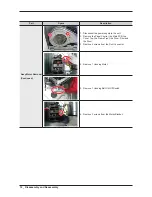
Page 24: ...4 screws from the Air Duct Be careful of the frame edge Duct Exhaust Removal 1 Disconnect the power supply to the unit 2 Remove 1 screws from the Back Cover 3 Remove 1 screw from the Duct Exhaust In case the screws for fixing a power code are dropped into the dryer after removing Duct Exhaust you can put it out through the hole ...

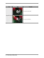
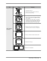
Page 25: ... the screw on the opposite side from the lever holder 5 Assemble the lever holder using the screws that were removed from the lever holder in Step 4 and then fasten the screw marked by the circle in the figure to the opposite side from the lever holder 6 Remove the two screws from the Frame Front 7 Fasten the screw into the hole on the other side 8 Remove 2 Cushion Cover F s from the bottom 9 Remov...

Page 26: ...crew insert the removed screw into the bottom hole and then fasten it 14 Assemble the Support Hinge and the Hinges that you removed in Step 12 as shown by the figure below 15 Fasten the 8 screws that you removed in Step 11 16 Install 2 Guide Holder Glasses onto the other side 17 Assemble the Holder Glass by sliding it so that the upper hook is caught and fasten the 15 screws that you removed in St...

Page 27: ...ilure to do so may result in the malfunction Store the removed Cushion Cover F in a safe location When you change the direction in which the door opens so that the door opens to the left you have to install the Cushion Cover F onto the door again 21 Install the door onto the Frame Front and fasten 2 screws that you removed in Step 2 Reassembly procedures are in the reverse order of dissasembly pro...

Page 28: ...26 _ Disassembly and Reassembly memo ...

Page 29: ...r Close the door and then restart dF Door is not closing properly Check for Check the door switch bE2 Unit detects a button is being pressed for over 30secs or button is stuck Check for Make sure a button is NOT being pressed continuously Try restarting the cycle hE Invalid heating Temp Check for Check the Heater thermistor In the case of gas model check for the gas is supplied continually Et EEPR...

Page 30: ...to sensor bar touch data mode Dryer will display Sensor Bar data This mode is default mode of entering service mode How to Enter With Power On pressing Wrinkle Prevent and Temp Keys for 3 seconds Cycle Count Mode Definition of Cycle Count Mode This mode is to bring up the total number of cycles that User have carried out How to Enter To enter cycle count mode press the Wrinkle Prevent in Service M...

Page 31: ...rt working at PCB Power supply plug 2 Since AC220 240V is applied to the triac T1 and T2 on P C B the electric shock may occur by touching Be careful the strong and weak electricity are mixed each other 3 As the P C B assembly is designed for no trouble do not replace the P C B assembly by the wrong diagnosis and follow the procedure of the trouble diagnosis when the micom is not operated normally...

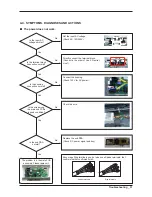
Page 32: ... control L1 supply 9 Igniter glows No gas ignition If the igniter heats up but the main burner flame is not ignited remove power and using an ohmmeter check the following Open secondary coil Open holding coil Open wire harness Stuck flame sensor Stuck closed 10 The gas is ignited but the flame goes out If a normal ignition takes place and after a short while the flame goes out check for the follow...

Page 33: ...tral Live 1 Neutral Earth L2 L1 Connect the housing Check 120V for AC power Check the wire Replace the sub PBA Check DC power signal and key Encourage Ring terminals use but when use Spade terminals that confirm whether confirmed finish Ring terminals Spade terminals Is the input AC voltage normal Yes No Is the sub PBA normal Yes No Is the terminal block connection normal Yes No Is the housing con...

Page 34: ...k whether it is 0Ω when the power is unplugged 1 Check the belt cut S W and connected condition Normal Check whether it is 0Ω when the power is unplugged 2 Check the connected condition of the motor idler and drum belt Belt cut off S W Is the Start button on Yes No Is the connected condition of the belt normal Yes No Is the door closed properly Yes No Is the connection to the door S W normal Yes N...

Page 35: ...Bar Temperature Sensor check Is the vent properly installed Yes No Check the Safety Hi Limit thermostat Check the cause of safety being off Did you clean the filter before drying Yes No Is the terminal block connection normal Yes No Is the touch sensor normal Yes No Is the Tamp Sensor normal Yes No Is the safety Hi limit thermostat normal Yes No Is the heater normal Yes No Replace the thermistor C...

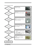
Page 36: ...L1 Replace the door S W Door operation of door S W Connect the power properly Check the connection between terminal block and door S W COM NO NC Replace the lamp Check for disconnection of lamp and socket Is the door S W structurally on off Yes No Is the power connection normal Yes No Is the lamp normal Yes No ...

Page 37: ...se come from the drum No Yes 1 Check the rotating part of the idler Idler bracket bending bracket screw 2 Remove any alien particle on the wings of the fan Noise can be generated from the unbalance of the fan due to alien particle on the fan Check the tightened condition of the nut Is there an abnormal noise in the motor part No Yes 1 Noise from drum back and heater duct movement Change the contac...

Page 38: ...at 3 Thermostat 2 resistance 1Ω If resistance is infinity replace thermostat 2 Heater resistance 10 Ω If resistance is infinity replace Heater THERMOSTAT 2 THERMOSTAT 3 HEATER Measure resistance of the following terminal 1 Door switch knob open Terminal COM NC 1 3 1Ω Terminal COM NO 1 2 Ω 2 Door switch push On Terminal COM NC 1 3 Ω Terminal COM NO 1 2 1Ω Door S W 125V 10A Belt Cut off S W Lever op...

Page 39: ...If resistance is infinite replace Igniter 120V 4 5A Gas Valve 25M01A Valve 1 2 Resistance value 1 2K Ω Valve 1 3 Resistance value 0 5K Ω Valve 4 5 Resistance value 1 2K Ω If resistance is infinity replace Valve 120V 60 Hz 120A Thermostat 60T21 Hi Limit 230F 50F Resistance value 1 Ω If resistance is infinity replace Thermostat 120V 20A 60T2 2 88Ω between Pin 3 and 4 3 5Ω between Pin 4 and 5 ...

Page 40: ...check Sensor Bars Disconnect harness and test Pink wire Pin 4 to Orange wire Pin 5 Approx Ω without laundry Approx 190Ω 10 with wet clothes Cycling thermistor Disconnect harness and test Blue wire Pin 3 to Red wire Pin 6 Approx 10 KΩ at 25 C 77 F CN6 6 1 ...

Page 41: ...arts Type 1 materials can be used for all Samsung Electronics products Most electrical parts belong to this type ex 0204 000418 FREON Type 2 Division wide parts DC Washing machine Type 2 materials can be used for specific products Most instruments and tools belong to this type ex DC96 01390A ASSY CONTROL 2 Ass y Materials All ass y material codes start with DC9 An ass y material is created by comb...

Page 42: ...s and Parts list 5 1 MAIN 6 4 3 6 4 2 1 2 20 1 20 2 20 1 1 1 1 6 4 1 18 1 18 2 1 20 3 0 2 4 12 14 21 22 GAS GAS Electric Power Cord 23 Electric 6 1 Option 19 8 7 16 Electric 15 18 17 2 17 1 17 6 3 6 2 6 4 6 5 11 13 9 10 ...

Page 43: ...2 000520 SCREW TAPPING TH 2 M4 L12 ZPC WHT SWRCH18A 2 PC SA 7 DC93 00153B ASSY M WIRE HARNESS ORCA DRYER 120V DC LAMP STEAM ELEC 1 PC SA 8 DC97 16738A ASSY PANEL CONTROL ORCA DRYER DV5471AEP XAA INOX 1 PC SNA 9 DC97 16755A ASSY DOOR ORCA DRYER DV5471AEP XAA INOX 1 PC SNA 10 DC97 16756A ASSY FRAME FRONT ORCA DRYER DV5471AEP XAA INOX 1 PC SNA 11 DC97 16757A ASSY DRUM FRONT ORCA DRYER DV5471AEP XAA 1...

Page 44: ...C SNA 6 4 3 6002 000520 SCREW TAPPING TH 2 M4 L12 ZPC WHT SWRCH18A 2 PC SA 7 DC93 00153B ASSY M WIRE HARNESS ORCA DRYER 120V DC LAMP STEAM ELEC 1 PC SA 8 DC90 06971A ASSY PANEL CONTROL ORCA DRYER DV5471AEW XAA 1 PC SNA 9 DC97 16794A ASSY DOOR ORCA DV5471AEW XAA 1 PC SNA 10 DC97 16791A ASSY FRAME FRONT ORCA DRYER DV5471AEW XAA 1 PC SNA 11 DC97 16757A ASSY DRUM FRONT ORCA DRYER DV5471AEP XAA 1 PC SN...

Page 45: ...NA 6 4 3 6002 000520 SCREW TAPPING TH 2 M4 L12 ZPC WHT SWRCH18A 2 PC SA 7 DC93 00153B ASSY M WIRE HARNESS ORCA DRYER 120V DC LAMP STEAM ELEC 1 PC SA 8 DC90 07100A ASSY PANEL CONTROL ORCA DRYER DV5451AEW XAA 1 PC SNA 9 DC97 16827A ASSY DOOR ORCA DRYER DV5451AEW XAA 1 PC SNA 10 DC97 16791A ASSY FRAME FRONT ORCA DRYER DV5471AEW XAA 1 PC SNA 11 DC97 16757A ASSY DRUM FRONT ORCA DRYER DV5471AEP XAA 1 PC...

Page 46: ...YER 120 DC LAMP STEAM GAS 1 PC SNA 8 DC90 06951A ASSY PANEL CONTROL ORCA DRYER DV5471AGP XAA 1 PC SNA 9 DC97 16755A ASSY DOOR ORCA DRYER DV5471AEP XAA INOX 1 PC SNA 10 DC97 16756A ASSY FRAME FRONT ORCA DRYER DV5471AEP XAA INOX 1 PC SNA 11 DC97 16757A ASSY DRUM FRONT ORCA DRYER DV5471AEP XAA 1 PC SNA 12 DC97 16758A ASSY DRUM WRAPPER ORCA DRYER DV5471AEP XAA 1 PC SNA 13 DC97 16789A ASSY DRUM BACK OR...

Page 47: ...ARNESS ORCA DRYER 120 DC LAMP STEAM GAS 1 PC SNA 8 DC90 07016A ASSY PANEL CONTROL ORCA DRYER DV5471AGW XAA 1 PC SNA 9 DC97 16794A ASSY DOOR ORCA DV5471AEW XAA 1 PC SNA 10 DC97 16791A ASSY FRAME FRONT ORCA DRYER DV5471AEW XAA 1 PC SNA 11 DC97 16757A ASSY DRUM FRONT ORCA DRYER DV5471AEP XAA 1 PC SNA 12 DC97 16758A ASSY DRUM WRAPPER ORCA DRYER DV5471AEP XAA 1 PC SNA 13 DC97 16789A ASSY DRUM BACK ORCA...

Page 48: ...ESS ORCA DRYER 120 DC LAMP STEAM GAS 1 PC SNA 8 DC90 07101A ASSY PANEL CONTROL ORCA DRYER DV5451AGW XAA 1 PC SNA 9 DC97 16827A ASSY DOOR ORCA DRYER DV5451AEW XAA 1 PC SNA 10 DC97 16791A ASSY FRAME FRONT ORCA DRYER DV5471AEW XAA 1 PC SNA 11 DC97 16757A ASSY DRUM FRONT ORCA DRYER DV5471AEP XAA 1 PC SNA 12 DC97 16812A ASSY DRUM WRAPPER ORCA DRYER DV5451AEW XAA 1 PC SNA 13 DC97 16814A ASSY DRUM BACK O...

Page 49: ...Exploded views and Parts list _ 47 memo ...

Page 50: ...oor 2 1 2 2 0 2 2 3 1 2 5 1 2 17 1 2 16 1 2 12 1 2 19 1 2 13 1 2 6 1 2 7 1 2 9 1 2 14 1 2 2 1 1 1 1 2 3 1 2 4 1 2 20 1 2 10 1 2 18 1 2 1 1 2 8 2 2 6 2 2 4 2 2 11 2 2 7 2 2 2 2 2 9 2 2 1 2 2 10 2 2 2 1 2 1 2 11 1 2 15 2 2 5 2 2 8 2 2 2 5 2 1 2 2 12 2 2 12 2 2 2 ...

Page 51: ...7 8 NTR ORCA PJT 2 PC SNA 1 2 9 DC61 03136A HINGE DOOR DV5471AEP ALDC T2 5 W32 0 L210 0 GRAY 1 PC SNA 1 2 10 DC62 00320A SEAL AIR DV5471AEP TPE GRAY W450 8 L424 0 5045N 1 PC SA 1 2 11 DC63 00613B CUSHION COVER F SEW 6HR129AT SILICON GRY 2 PC SA 1 2 12 DC63 01326A COVER DOOR DV5471AEP ABS T3 0 W548 2 L489 7 INOX 1 PC SA 1 2 13 DC63 01327A COVER DOOR I DV5471AEP ABS W480 9 L371 2 INOX ORCA 1 PC SNA ...

Page 52: ...R GI SGCC T1 4 W400 NTR DV5471AEP XAA 1 PC SNA 2 2 5 DC61 03133A GUIDE COVER TOP DV5471AEP PA L10 0 Zytel FR50 BLK 4 PC SA 2 2 6 DC61 03135A BRACKET HINGE L DV5471AEP HGI SGHC T1 4 L300 NTR 1 PC SA 2 2 7 DC61 03169A BASE DV5471AEP ABS W682 0 H31 2 BLK 1 PC SNA 2 2 8 DC61 03174A FIXER COVER TOP DV5471AEP XAA SK5 T0 8 W19 0 H21 9 NTR ORCA PJT 2 PC SA 2 2 9 DC64 00828B DOOR S W SPE110F 1D3 NYLON T13 ...

Page 53: ...SNA 1 2 10 DC62 00320A SEAL AIR DV5471AEP TPE GRAY W450 8 L424 0 5045N 1 PC SA 1 2 11 DC63 00613B CUSHION COVER F SEW 6HR129AT SILICON GRY 2 PC SA 1 2 12 DC63 01326B COVER DOOR DV5471AEW XAA ABS T3 0 W548 2 L489 7 NEAT WHITE 1 PC SA 1 2 13 DC63 01327B COVER DOOR I DV5417AEW XAA ABS W480 9 L371 2 NEAT WHT 1 PC SNA 1 2 14 DC63 01362A COVER HINGE DV5471AEP PET T0 188 W34 0 L212 0 NTR 1 PC SNA 1 2 15 ...

Page 54: ...VER TOP DV5471AEP PA L10 0 Zytel FR50 BLK 4 PC SA 2 2 6 DC61 03135A BRACKET HINGE L DV5471AEP HGI SGHC T1 4 L300 NTR 1 PC SA 2 2 7 DC61 03169A BASE DV5471AEP ABS W682 0 H31 2 BLK 1 PC SNA 2 2 8 DC61 03174A FIXER COVER TOP DV5471AEP XAA SK5 T0 8 W19 0 H21 9 NTR ORCA PJT 2 PC SA 2 2 9 DC64 00828B DOOR S W SPE110F 1D3 NYLON T13 6 H44 W44 3 WHT 125 250V 10A 1 PC SA 2 2 10 DC97 07510B ASSY HOLDER LEVER...

Page 55: ...GRAY 1 PC SNA 1 2 10 DC62 00320A SEAL AIR DV5471AEP TPE GRAY W450 8 L424 0 5045N 1 PC SA 1 2 11 DC63 00613B CUSHION COVER F SEW 6HR129AT SILICON GRY 2 PC SA 1 2 12 DC63 01326B COVER DOOR DV5471AEW XAA ABS T3 0 W548 2 L489 7 NEAT WHITE 1 PC SA 1 2 13 DC63 01327B COVER DOOR I DV5417AEW XAA ABS W480 9 L371 2 NEAT WHT 1 PC SNA 1 2 14 DC63 01362A COVER HINGE DV5471AEP PET T0 188 W34 0 L212 0 NTR 1 PC S...

Page 56: ...VER TOP DV5471AEP PA L10 0 Zytel FR50 BLK 4 PC SA 2 2 6 DC61 03135A BRACKET HINGE L DV5471AEP HGI SGHC T1 4 L300 NTR 1 PC SA 2 2 7 DC61 03169A BASE DV5471AEP ABS W682 0 H31 2 BLK 1 PC SNA 2 2 8 DC61 03174A FIXER COVER TOP DV5471AEP XAA SK5 T0 8 W19 0 H21 9 NTR ORCA PJT 2 PC SA 2 2 9 DC64 00828B DOOR S W SPE110F 1D3 NYLON T13 6 H44 W44 3 WHT 125 250V 10A 1 PC SA 2 2 10 DC97 07510B ASSY HOLDER LEVER...

Page 57: ...C62 00320A SEAL AIR DV5471AEP TPE GRAY W450 8 L424 0 5045N 1 PC SA 1 2 11 DC63 00613B CUSHION COVER F SEW 6HR129AT SILICON GRY 2 PC SA 1 2 12 DC63 01326A COVER DOOR DV5471AEP ABS T3 0 W548 2 L489 7 INOX 1 PC SA 1 2 13 DC63 01327A COVER DOOR I DV5471AEP ABS W480 9 L371 2 INOX ORCA 1 PC SNA 1 2 14 DC63 01362A COVER HINGE DV5471AEP PET T0 188 W34 0 L212 0 NTR 1 PC SNA 1 2 15 DC63 01396A CUSHION COVER...

Page 58: ...0 BLK 4 PC SA 2 2 6 DC61 03135A BRACKET HINGE L DV5471AEP HGI SGHC T1 4 L300 NTR 1 PC SA 2 2 7 DC61 03169A BASE DV5471AEP ABS W682 0 H31 2 BLK 1 PC SNA 2 2 8 DC61 03174A FIXER COVER TOP DV5471AEP XAA SK5 T0 8 W19 0 H21 9 NTR ORCA PJT 2 PC SA 2 2 9 DC64 00828B DOOR S W SPE110F 1D3 NYLON T13 6 H44 W44 3 WHT 125 250V 10A 1 PC SA 2 2 10 DC97 07510B ASSY HOLDER LEVER MDE7800AYW DRYER DOOR LOCK 1 PC SA ...

Page 59: ...SNA 1 2 10 DC62 00320A SEAL AIR DV5471AEP TPE GRAY W450 8 L424 0 5045N 1 PC SA 1 2 11 DC63 00613B CUSHION COVER F SEW 6HR129AT SILICON GRY 2 PC SA 1 2 12 DC63 01326B COVER DOOR DV5471AEW XAA ABS T3 0 W548 2 L489 7 NEAT WHITE 1 PC SA 1 2 13 DC63 01327B COVER DOOR I DV5417AEW XAA ABS W480 9 L371 2 NEAT WHT 1 PC SNA 1 2 14 DC63 01362A COVER HINGE DV5471AEP PET T0 188 W34 0 L212 0 NTR 1 PC SNA 1 2 15 ...

Page 60: ...VER TOP DV5471AEP PA L10 0 Zytel FR50 BLK 4 PC SA 2 2 6 DC61 03135A BRACKET HINGE L DV5471AEP HGI SGHC T1 4 L300 NTR 1 PC SA 2 2 7 DC61 03169A BASE DV5471AEP ABS W682 0 H31 2 BLK 1 PC SNA 2 2 8 DC61 03174A FIXER COVER TOP DV5471AEP XAA SK5 T0 8 W19 0 H21 9 NTR ORCA PJT 2 PC SA 2 2 9 DC64 00828B DOOR S W SPE110F 1D3 NYLON T13 6 H44 W44 3 WHT 125 250V 10A 1 PC SA 2 2 10 DC97 07510B ASSY HOLDER LEVER...

Page 61: ...GRAY 1 PC SNA 1 2 10 DC62 00320A SEAL AIR DV5471AEP TPE GRAY W450 8 L424 0 5045N 1 PC SA 1 2 11 DC63 00613B CUSHION COVER F SEW 6HR129AT SILICON GRY 2 PC SA 1 2 12 DC63 01326B COVER DOOR DV5471AEW XAA ABS T3 0 W548 2 L489 7 NEAT WHITE 1 PC SA 1 2 13 DC63 01327B COVER DOOR I DV5417AEW XAA ABS W480 9 L371 2 NEAT WHT 1 PC SNA 1 2 14 DC63 01362A COVER HINGE DV5471AEP PET T0 188 W34 0 L212 0 NTR 1 PC S...

Page 62: ...VER TOP DV5471AEP PA L10 0 Zytel FR50 BLK 4 PC SA 2 2 6 DC61 03135A BRACKET HINGE L DV5471AEP HGI SGHC T1 4 L300 NTR 1 PC SA 2 2 7 DC61 03169A BASE DV5471AEP ABS W682 0 H31 2 BLK 1 PC SNA 2 2 8 DC61 03174A FIXER COVER TOP DV5471AEP XAA SK5 T0 8 W19 0 H21 9 NTR ORCA PJT 2 PC SA 2 2 9 DC64 00828B DOOR S W SPE110F 1D3 NYLON T13 6 H44 W44 3 WHT 125 250V 10A 1 PC SA 2 2 10 DC97 07510B ASSY HOLDER LEVER...

Page 63: ...Exploded views and Parts list _ 61 memo ...

Page 64: ...62 _ Exploded views and Parts list 5 3 Ass y Panel Control 0 1 2 4 1 3 6 3 6 2 6 1 6 4 6 5 6 5 3 5 2 5 1 5 ...

Page 65: ...C92 00621B ASSY PCB SUB ORCA DRYER SUB S PBA 120V 220V 50 60HZ DSP N 1 PC SA 5 DC97 16068B ASSY KNOB ENCODER EAGLE PJT SQUALL NO PEARL NO SPRING 1 PC SA 5 1 DC64 01642D KNOB ENCODER HELIOS C ABS T2 0 NO PEARL SILVER NO SPRING 1 PC SNA 5 2 DC64 02222A DECORATION ENCODER WF350ANW XAA ABS T6 0 W67 6 NTR SQUALL 1 PC SNA 5 3 DC64 02223A DECORATION ENCODER I WF350ANW XAA ABS T2 0 W57 7 NTR SQUALL 1 PC S...

Page 66: ... 00621B ASSY PCB SUB ORCA DRYER SUB S PBA 120V 220V 50 60HZ DSP N 1 PC SA 5 DC97 16068B ASSY KNOB ENCODER EAGLE PJT SQUALL NO PEARL NO SPRING 1 PC SA 5 1 DC64 01642D KNOB ENCODER HELIOS C ABS T2 0 NO PEARL SILVER NO SPRING 1 PC SNA 5 2 DC64 02222A DECORATION ENCODER WF350ANW XAA ABS T6 0 W67 6 NTR SQUALL 1 PC SNA 5 3 DC64 02223A DECORATION ENCODER I WF350ANW XAA ABS T2 0 W57 7 NTR SQUALL 1 PC SNA ...

Page 67: ... ASSY PCB SUB ORCA BETTER SUB DISPLAY 120V 220V 50 60HZ N 1 PC SA 5 DC97 16068B ASSY KNOB ENCODER EAGLE PJT SQUALL NO PEARL NO SPRING 1 PC SA 5 1 DC64 01642D KNOB ENCODER HELIOS C ABS T2 0 NO PEARL SILVER NO SPRING 1 PC SNA 5 2 DC64 02222A DECORATION ENCODER WF350ANW XAA ABS T6 0 W67 6 NTR SQUALL 1 PC SNA 5 3 DC64 02223A DECORATION ENCODER I WF350ANW XAA ABS T2 0 W57 7 NTR SQUALL 1 PC SNA 6 DC97 1...

Page 68: ...2 00621B ASSY PCB SUB ORCA DRYER SUB S PBA 120V 220V 50 60HZ DSP N 1 PC SA 5 DC97 16068B ASSY KNOB ENCODER EAGLE PJT SQUALL NO PEARL NO SPRING 1 PC SA 5 1 DC64 01642D KNOB ENCODER HELIOS C ABS T2 0 NO PEARL SILVER NO SPRING 1 PC SNA 5 2 DC64 02222A DECORATION ENCODER WF350ANW XAA ABS T6 0 W67 6 NTR SQUALL 1 PC SNA 5 3 DC64 02223A DECORATION ENCODER I WF350ANW XAA ABS T2 0 W57 7 NTR SQUALL 1 PC SNA...

Page 69: ... 00621B ASSY PCB SUB ORCA DRYER SUB S PBA 120V 220V 50 60HZ DSP N 1 PC SA 5 DC97 16068B ASSY KNOB ENCODER EAGLE PJT SQUALL NO PEARL NO SPRING 1 PC SA 5 1 DC64 01642D KNOB ENCODER HELIOS C ABS T2 0 NO PEARL SILVER NO SPRING 1 PC SNA 5 2 DC64 02222A DECORATION ENCODER WF350ANW XAA ABS T6 0 W67 6 NTR SQUALL 1 PC SNA 5 3 DC64 02223A DECORATION ENCODER I WF350ANW XAA ABS T2 0 W57 7 NTR SQUALL 1 PC SNA ...

Page 70: ...ASSY PCB SUB ORCA BETTER SUB DISPLAY 120V 220V 50 60HZ N 1 PC SA 5 DC97 16068B ASSY KNOB ENCODER EAGLE PJT SQUALL NO PEARL NO SPRING 1 PC SA 5 1 DC64 01642D KNOB ENCODER HELIOS C ABS T2 0 NO PEARL SILVER NO SPRING 1 PC SNA 5 2 DC64 02222A DECORATION ENCODER WF350ANW XAA ABS T6 0 W67 6 NTR SQUALL 1 PC SNA 5 3 DC64 02223A DECORATION ENCODER I WF350ANW XAA ABS T2 0 W57 7 NTR SQUALL 1 PC SNA 6 DC97 16...

Page 71: ...Exploded views and Parts list _ 69 memo ...

Page 72: ...8 1 1 2 8 2 1 2 5 1 0 2 2 3 1 2 4 3 2 4 2 2 2 4 2 1 1 2 1 1 2 4 1 1 1 2 5 1 1 1 2 2 1 2 3 1 1 1 2 7 1 1 2 7 4 1 2 7 2 1 2 7 3 1 2 9 1 2 7 1 1 2 8 1 2 6 1 2 6 2 1 2 6 3 1 2 6 4 1 2 6 5 1 2 6 1 3 4 3 10 3 10 1 3 10 2 3 10 4 3 10 3 3 3 3 7 3 6 3 8 3 1 3 2 3 3 3 9 3 9 1 3 5 ...

Page 73: ...337AEW GI T0 6 NTR 2 HOLES 1 PC SNA 1 2 6 4 DC72 00032A ABSORBER SPONGE MDE9700AYW EPDM T5 W20 L400 BLK DUCT OUTLET F 1 PC SNA 1 2 6 5 DC72 00032C ABSORBER SPONGE MDE9700AYW EPDM T5 W20 L380 BLK DUCT OUTLET B 1 PC SNA 1 2 7 DC97 16741A ASSY COVER FILTER ORCA DRYER DV5471AEP XAA 1 PC SNA 1 2 7 1 DC61 02627A PLATE SENSOR DV220AEW STAINLESS STS430 T0 8 TOUCH SENSOR 2 PC SA 1 2 7 2 DC63 01319A COVER F...

Page 74: ...2826A BRACKET DRUM BACK B DV520AEP XAA GI T0 8 1 PC SA 3 6 DC61 03130A BRACKET DRUM BACK DV5471AEP EGI SECC T1 0 L299 0 NTR 1 PC SA 3 7 DC66 00411C DRUM BACK DV331AEW EGI SECC T0 6 GRAY 1 PC SA 3 8 DC97 07521A ASSY DUCT AIR MDE7800AYW DRYER ELECTRIC 1 PC SA 3 9 DC97 07523B ASSY ROLLER 27 DRYER DRYER EPDM 2 PC SA 3 9 1 DC61 01228A HOLDER SHAFT WINGS DRYER NYLON 6 NTR ROLLER 2 PC SA 3 10 DC97 14929B...

Page 75: ...337AEW GI T0 6 NTR 2 HOLES 1 PC SNA 1 2 6 4 DC72 00032A ABSORBER SPONGE MDE9700AYW EPDM T5 W20 L400 BLK DUCT OUTLET F 1 PC SNA 1 2 6 5 DC72 00032C ABSORBER SPONGE MDE9700AYW EPDM T5 W20 L380 BLK DUCT OUTLET B 1 PC SNA 1 2 7 DC97 16741A ASSY COVER FILTER ORCA DRYER DV5471AEP XAA 1 PC SNA 1 2 7 1 DC61 02627A PLATE SENSOR DV220AEW STAINLESS STS430 T0 8 TOUCH SENSOR 2 PC SA 1 2 7 2 DC63 01319A COVER F...

Page 76: ...26A BRACKET DRUM BACK B DV520AEP XAA GI T0 8 1 PC SA 3 6 DC61 03130A BRACKET DRUM BACK DV5471AEP EGI SECC T1 0 L299 0 NTR 1 PC SA 3 7 DC66 00411C DRUM BACK DV331AEW EGI SECC T0 6 GRAY 1 PC SA 3 8 DC97 07521A ASSY DUCT AIR MDE7800AYW DRYER ELECTRIC 1 PC SA 3 9 DC97 07523B ASSY ROLLER 27 DRYER DRYER EPDM 2 PC SA 3 9 1 DC61 01228A HOLDER SHAFT WINGS DRYER NYLON 6 NTR ROLLER 2 PC SA 3 10 DC97 14929B A...

Page 77: ...37AEW GI T0 6 NTR 2 HOLES 1 PC SNA 1 2 6 4 DC72 00032A ABSORBER SPONGE MDE9700AYW EPDM T5 W20 L400 BLK DUCT OUTLET F 1 PC SNA 1 2 6 5 DC72 00032C ABSORBER SPONGE MDE9700AYW EPDM T5 W20 L380 BLK DUCT OUTLET B 1 PC SNA 1 2 7 DC97 16741A ASSY COVER FILTER ORCA DRYER DV5471AEP XAA 1 PC SNA 1 2 7 1 DC61 02627A PLATE SENSOR DV220AEW STAINLESS STS430 T0 8 TOUCH SENSOR 2 PC SA 1 2 7 2 DC63 01319A COVER FI...

Page 78: ...KET DRUM BACK B DV520AEP XAA GI T0 8 1 PC SA 3 6 DC61 03130A BRACKET DRUM BACK DV5471AEP EGI SECC T1 0 L299 0 NTR 1 PC SA 3 7 DC66 00411E DRUM BACK DV5451AEW XAA EGI SECC T0 6 NEAT WHITE STEAM 1 PC SA 3 8 DC97 07521A ASSY DUCT AIR MDE7800AYW DRYER ELECTRIC 1 PC SA 3 9 DC97 07523B ASSY ROLLER 27 DRYER DRYER EPDM 2 PC SA 3 9 1 DC61 01228A HOLDER SHAFT WINGS DRYER NYLON 6 NTR ROLLER 2 PC SA 3 10 DC97...

Page 79: ...337AEW GI T0 6 NTR 2 HOLES 1 PC SNA 1 2 6 4 DC72 00032A ABSORBER SPONGE MDE9700AYW EPDM T5 W20 L400 BLK DUCT OUTLET F 1 PC SNA 1 2 6 5 DC72 00032C ABSORBER SPONGE MDE9700AYW EPDM T5 W20 L380 BLK DUCT OUTLET B 1 PC SNA 1 2 7 DC97 16741A ASSY COVER FILTER ORCA DRYER DV5471AEP XAA 1 PC SNA 1 2 7 1 DC61 02627A PLATE SENSOR DV220AEW STAINLESS STS430 T0 8 TOUCH SENSOR 2 PC SA 1 2 7 2 DC63 01319A COVER F...

Page 80: ...A BRACKET DRUM BACK B DV520AEP XAA GI T0 8 1 PC SA 3 6 DC61 03130A BRACKET DRUM BACK DV5471AEP EGI SECC T1 0 L299 0 NTR 1 PC SA 3 7 DC66 00411C DRUM BACK DV331AEW EGI SECC T0 6 GRAY 1 PC SA 3 8 DC97 07521C ASSY DUCT AIR MDG9700AWW GAS DRYER WING TYPE 1 PC SA 3 9 DC97 07523B ASSY ROLLER 27 DRYER DRYER EPDM 2 PC SA 3 9 1 DC61 01228A HOLDER SHAFT WINGS DRYER NYLON 6 NTR ROLLER 2 PC SA 3 10 DC97 14929...

Page 81: ...337AEW GI T0 6 NTR 2 HOLES 1 PC SNA 1 2 6 4 DC72 00032A ABSORBER SPONGE MDE9700AYW EPDM T5 W20 L400 BLK DUCT OUTLET F 1 PC SNA 1 2 6 5 DC72 00032C ABSORBER SPONGE MDE9700AYW EPDM T5 W20 L380 BLK DUCT OUTLET B 1 PC SNA 1 2 7 DC97 16741A ASSY COVER FILTER ORCA DRYER DV5471AEP XAA 1 PC SNA 1 2 7 1 DC61 02627A PLATE SENSOR DV220AEW STAINLESS STS430 T0 8 TOUCH SENSOR 2 PC SA 1 2 7 2 DC63 01319A COVER F...

Page 82: ...A BRACKET DRUM BACK B DV520AEP XAA GI T0 8 1 PC SA 3 6 DC61 03130A BRACKET DRUM BACK DV5471AEP EGI SECC T1 0 L299 0 NTR 1 PC SA 3 7 DC66 00411C DRUM BACK DV331AEW EGI SECC T0 6 GRAY 1 PC SA 3 8 DC97 07521C ASSY DUCT AIR MDG9700AWW GAS DRYER WING TYPE 1 PC SA 3 9 DC97 07523B ASSY ROLLER 27 DRYER DRYER EPDM 2 PC SA 3 9 1 DC61 01228A HOLDER SHAFT WINGS DRYER NYLON 6 NTR ROLLER 2 PC SA 3 10 DC97 14929...

Page 83: ...37AEW GI T0 6 NTR 2 HOLES 1 PC SNA 1 2 6 4 DC72 00032A ABSORBER SPONGE MDE9700AYW EPDM T5 W20 L400 BLK DUCT OUTLET F 1 PC SNA 1 2 6 5 DC72 00032C ABSORBER SPONGE MDE9700AYW EPDM T5 W20 L380 BLK DUCT OUTLET B 1 PC SNA 1 2 7 DC97 16741A ASSY COVER FILTER ORCA DRYER DV5471AEP XAA 1 PC SNA 1 2 7 1 DC61 02627A PLATE SENSOR DV220AEW STAINLESS STS430 T0 8 TOUCH SENSOR 2 PC SA 1 2 7 2 DC63 01319A COVER FI...

Page 84: ... DRUM BACK B DV520AEP XAA GI T0 8 1 PC SA 3 6 DC61 03130A BRACKET DRUM BACK DV5471AEP EGI SECC T1 0 L299 0 NTR 1 PC SA 3 7 DC66 00411E DRUM BACK DV5451AEW XAA EGI SECC T0 6 NEAT WHITE STEAM 1 PC SA 3 8 DC97 07521C ASSY DUCT AIR MDG9700AWW GAS DRYER WING TYPE 1 PC SA 3 9 DC97 07523B ASSY ROLLER 27 DRYER DRYER EPDM 2 PC SA 3 9 1 DC61 01228A HOLDER SHAFT WINGS DRYER NYLON 6 NTR ROLLER 2 PC SA 3 10 DC...

Page 85: ...Exploded views and Parts list _ 83 memo ...

Page 86: ... _ Exploded views and Parts list 5 5 Ass y Motor 2 7 3 2 7 2 2 8 2 2 8 1 2 7 1 2 9 7 4 1 0 1 2 9 2 8 2 9 4 2 2 2 5 2 9 1 2 9 1 2 9 2 2 9 7 2 2 9 3 2 9 7 3 2 9 7 4 2 9 7 1 2 9 7 2 2 9 6 2 7 2 1 2 6 2 4 2 3 ...

Page 87: ...W102 5 NTR TB53 1 PC SNA 2 7 3 DC63 01026A COVER DUCT FAN 27 DRYER GI T0 6 1 PC SNA 2 8 DC93 00282A ASSY DUCT CONNECTOR ORCA DRYER DV5471AEP 1 PC SA 2 8 1 DC67 00586A DUCT CONNECTOR DV5471AEP PP T2 5 NTR 1 PC SNA 2 8 2 DC72 00032E ABSORBER SPONGE MDE9700AYW EPDM T3 W15 L740 BLK C OVER FAN 1 PC SNA 2 9 DC96 00790C ASSY BRACKET MOTOR MDE9700AYW DRYER 1 PC SNA 2 9 1 3405 001077 SWITCH MICRO 125V 15A ...

Page 88: ...W102 5 NTR TB53 1 PC SNA 2 7 3 DC63 01026A COVER DUCT FAN 27 DRYER GI T0 6 1 PC SNA 2 8 DC93 00282A ASSY DUCT CONNECTOR ORCA DRYER DV5471AEP 1 PC SA 2 8 1 DC67 00586A DUCT CONNECTOR DV5471AEP PP T2 5 NTR 1 PC SNA 2 8 2 DC72 00032E ABSORBER SPONGE MDE9700AYW EPDM T3 W15 L740 BLK C OVER FAN 1 PC SNA 2 9 DC96 00790C ASSY BRACKET MOTOR MDE9700AYW DRYER 1 PC SNA 2 9 1 3405 001077 SWITCH MICRO 125V 15A ...

Page 89: ...W102 5 NTR TB53 1 PC SNA 2 7 3 DC63 01026A COVER DUCT FAN 27 DRYER GI T0 6 1 PC SNA 2 8 DC93 00282A ASSY DUCT CONNECTOR ORCA DRYER DV5471AEP 1 PC SA 2 8 1 DC67 00586A DUCT CONNECTOR DV5471AEP PP T2 5 NTR 1 PC SNA 2 8 2 DC72 00032E ABSORBER SPONGE MDE9700AYW EPDM T3 W15 L740 BLK C OVER FAN 1 PC SNA 2 9 DC96 00790C ASSY BRACKET MOTOR MDE9700AYW DRYER 1 PC SNA 2 9 1 3405 001077 SWITCH MICRO 125V 15A ...

Page 90: ... W102 5 NTR TB53 1 PC SNA 2 7 3 DC63 01026A COVER DUCT FAN 27 DRYER GI T0 6 1 PC SNA 2 8 DC93 00282A ASSY DUCT CONNECTOR ORCA DRYER DV5471AEP 1 PC SNA 2 8 1 DC67 00586A DUCT CONNECTOR DV5471AEP PP T2 5 NTR 1 PC SNA 2 8 2 DC72 00032E ABSORBER SPONGE MDE9700AYW EPDM T3 W15 L740 BLK C OVER FAN 1 PC SNA 2 9 DC96 00790C ASSY BRACKET MOTOR MDE9700AYW DRYER 1 PC SNA 2 9 1 3405 001077 SWITCH MICRO 125V 15...

Page 91: ... W102 5 NTR TB53 1 PC SNA 2 7 3 DC63 01026A COVER DUCT FAN 27 DRYER GI T0 6 1 PC SNA 2 8 DC93 00282A ASSY DUCT CONNECTOR ORCA DRYER DV5471AEP 1 PC SNA 2 8 1 DC67 00586A DUCT CONNECTOR DV5471AEP PP T2 5 NTR 1 PC SNA 2 8 2 DC72 00032E ABSORBER SPONGE MDE9700AYW EPDM T3 W15 L740 BLK C OVER FAN 1 PC SNA 2 9 DC96 00790C ASSY BRACKET MOTOR MDE9700AYW DRYER 1 PC SNA 2 9 1 3405 001077 SWITCH MICRO 125V 15...

Page 92: ... W102 5 NTR TB53 1 PC SNA 2 7 3 DC63 01026A COVER DUCT FAN 27 DRYER GI T0 6 1 PC SNA 2 8 DC93 00282A ASSY DUCT CONNECTOR ORCA DRYER DV5471AEP 1 PC SNA 2 8 1 DC67 00586A DUCT CONNECTOR DV5471AEP PP T2 5 NTR 1 PC SNA 2 8 2 DC72 00032E ABSORBER SPONGE MDE9700AYW EPDM T3 W15 L740 BLK C OVER FAN 1 PC SNA 2 9 DC96 00790C ASSY BRACKET MOTOR MDE9700AYW DRYER 1 PC SNA 2 9 1 3405 001077 SWITCH MICRO 125V 15...

Page 93: ...Exploded views and Parts list _ 91 memo ...

Page 94: ...92 _ Exploded views and Parts list 5 6 Ass y Duct Heater 1 8 1 0 2 1 6 1 1 1 4 1 8 1 7 1 3 1 2 1 5 1 1 1 1 1 1 8 2 ...

Page 95: ...M4 L14 ZPC WHT SWRCH18A 1 PC SA 1 3 DC47 00018A THERMOSTAT 60T11 250V 25A 20 150 30 150 25A 23 6 100M 260F 50F HI LIMIT 1 PC SA 1 4 DC47 00019A HEATER DRY GD PJT 5300W 21A 240 10 D1 3 240V5300 1 PC SA 1 5 DC65 00013A TERMINAL BLOCK GR PJT SERAMIC 2HOLE 1015 AWG 12 16 76 WHT HEATER 1 PC SNA 1 6 DC67 00132A DUCT HEATER U WINGS DRYER AL COAT T0 5 NTR UPPER 1 PC SNA 1 7 DC67 00133A DUCT HEATER L WINGS...

Page 96: ...M4 L14 ZPC WHT SWRCH18A 1 PC SA 1 3 DC47 00018A THERMOSTAT 60T11 250V 25A 20 150 30 150 25A 23 6 100M 260F 50F HI LIMIT 1 PC SA 1 4 DC47 00019A HEATER DRY GD PJT 5300W 21A 240 10 D1 3 240V5300 1 PC SA 1 5 DC65 00013A TERMINAL BLOCK GR PJT SERAMIC 2HOLE 1015 AWG 12 16 76 WHT HEATER 1 PC SNA 1 6 DC67 00132A DUCT HEATER U WINGS DRYER AL COAT T0 5 NTR UPPER 1 PC SNA 1 7 DC67 00133A DUCT HEATER L WINGS...

Page 97: ...M4 L14 ZPC WHT SWRCH18A 1 PC SA 1 3 DC47 00018A THERMOSTAT 60T11 250V 25A 20 150 30 150 25A 23 6 100M 260F 50F HI LIMIT 1 PC SA 1 4 DC47 00019A HEATER DRY GD PJT 5300W 21A 240 10 D1 3 240V5300 1 PC SA 1 5 DC65 00013A TERMINAL BLOCK GR PJT SERAMIC 2HOLE 1015 AWG 12 16 76 WHT HEATER 1 PC SNA 1 6 DC67 00132A DUCT HEATER U WINGS DRYER AL COAT T0 5 NTR UPPER 1 PC SNA 1 7 DC67 00133A DUCT HEATER L WINGS...

Page 98: ...96 _ Exploded views and Parts list 5 7 Ass y Duct Burner 0 2 1 1 4 1 2 1 1 1 3 1 1 1 4 2 1 4 3 1 4 1 2 3 2 5 5 4 2 4 2 2 2 1 2 6 3 6 7 ...

Page 99: ...ONE F WINGS DRYER AL COAT T0 6 NTR FRONT 1 PC SA 1 4 3 DC67 00137B DUCT CONE B WINGS DRYER AL COAT T0 6 NTR BACK 1 PC SA 2 DC97 14492A ASSY BURNER 1 PC SA 2 1 6006 001174 SCREW TAPPING TH WE 2S M4 L12 ZPC WHT SWR CH18A 3 PC SNA 2 2 6009 001476 SCREW HEX HEX M5 L10 ZPC WHT SWRCH18A 2 1 PC SA 2 3 DC61 01232A BRACKET BURNER WINGS DRYER SECC EGI T1 0 1 PC SA 2 4 DC62 00200A TUBE BURNER WINGS DRYER PRE...

Page 100: ...ONE F WINGS DRYER AL COAT T0 6 NTR FRONT 1 PC SA 1 4 3 DC67 00137B DUCT CONE B WINGS DRYER AL COAT T0 6 NTR BACK 1 PC SA 2 DC97 14492A ASSY BURNER 1 PC SA 2 1 6006 001174 SCREW TAPPING TH WE 2S M4 L12 ZPC WHT SWR CH18A 3 PC SNA 2 2 6009 001476 SCREW HEX HEX M5 L10 ZPC WHT SWRCH18A 2 1 PC SA 2 3 DC61 01232A BRACKET BURNER WINGS DRYER SECC EGI T1 0 1 PC SA 2 4 DC62 00200A TUBE BURNER WINGS DRYER PRE...

Page 101: ...ONE F WINGS DRYER AL COAT T0 6 NTR FRONT 1 PC SA 1 4 3 DC67 00137B DUCT CONE B WINGS DRYER AL COAT T0 6 NTR BACK 1 PC SA 2 DC97 14492A ASSY BURNER 1 PC SA 2 1 6006 001174 SCREW TAPPING TH WE 2S M4 L12 ZPC WHT SWR CH18A 3 PC SNA 2 2 6009 001476 SCREW HEX HEX M5 L10 ZPC WHT SWRCH18A 2 1 PC SA 2 3 DC61 01232A BRACKET BURNER WINGS DRYER SECC EGI T1 0 1 PC SA 2 4 DC62 00200A TUBE BURNER WINGS DRYER PRE...

Page 102: ...C SNA 2 DC61 00553C HOLDER WIRE SADDLE NYLON66 NTR DAWS 2NA ASSY FRAME FRONT 1 PC SA 3 DC61 40081A HOLDER WIRE DAWH 2NC PA NTR PI18 5 BOTTOM FRAME 2 PC SA 3 DC61 40081A HOLDER WIRE DAWH 2NC PA NTR PI18 5 PLATE BOTTOM 5 PC SA 3 DC61 40081A HOLDER WIRE DAWH 2NC PA NTR PI18 5 ASSY BRACKET SPRING L 1 PC SA 4 DC61 40086A HOLDER WIRE DAWH 3NB NYLON66 NTR PI15 COVER TOP 1 PC SA 5 6502 000127 CABLE CLAMP ...

Page 103: ...SNA 2 DC61 00553C HOLDER WIRE SADDLE NYLON66 NTR DAWS 2NA ASSY FRAME FRONT 1 PC SA 3 DC61 40081A HOLDER WIRE DAWH 2NC PA NTR PI18 5 BOTTOM FRAME 2 PC SA 3 DC61 40081A HOLDER WIRE DAWH 2NC PA NTR PI18 5 PLATE BOTTOM 5 PC SA 3 DC61 40081A HOLDER WIRE DAWH 2NC PA NTR PI18 5 ASSY BRACKET SPRING L 1 PC SA 4 DC61 40086A HOLDER WIRE DAWH 3NB NYLON66 NTR PI15 COVER TOP 1 PC SA 5 6502 000127 CABLE CLAMP DA...

Page 104: ...SNA 2 DC61 00553C HOLDER WIRE SADDLE NYLON66 NTR DAWS 2NA ASSY FRAME FRONT 1 PC SA 3 DC61 40081A HOLDER WIRE DAWH 2NC PA NTR PI18 5 BOTTOM FRAME 2 PC SA 3 DC61 40081A HOLDER WIRE DAWH 2NC PA NTR PI18 5 PLATE BOTTOM 5 PC SA 3 DC61 40081A HOLDER WIRE DAWH 2NC PA NTR PI18 5 ASSY BRACKET SPRING L 1 PC SA 4 DC61 40086A HOLDER WIRE DAWH 3NB NYLON66 NTR PI15 COVER TOP 1 PC SA 5 6502 000127 CABLE CLAMP DA...

Page 105: ... 1 PC SA 3 DC61 40081A HOLDER WIRE DAWH 2NC PA NTR PI18 5 ASSY PLATE BOTTOM 2 PC SA 3 DC61 40081A HOLDER WIRE DAWH 2NC PA NTR PI18 5 M WIER FRAME 2 PC SA 3 DC61 40081A HOLDER WIRE DAWH 2NC PA NTR PI18 5 POWER CORD FRAME 1 PC SA 3 DC61 40081A HOLDER WIRE DAWH 2NC PA NTR PI18 5 PLATE BOTTOM 5 PC SA 3 DC61 40081A HOLDER WIRE DAWH 2NC PA NTR PI18 5 ASSY BRACKET SPRING L 1 PC SA 4 DC61 40086A HOLDER WI...

Page 106: ... 1 PC SA 3 DC61 40081A HOLDER WIRE DAWH 2NC PA NTR PI18 5 ASSY PLATE BOTTOM 2 PC SA 3 DC61 40081A HOLDER WIRE DAWH 2NC PA NTR PI18 5 M WIER FRAME 2 PC SA 3 DC61 40081A HOLDER WIRE DAWH 2NC PA NTR PI18 5 POWER CORD FRAME 1 PC SA 3 DC61 40081A HOLDER WIRE DAWH 2NC PA NTR PI18 5 PLATE BOTTOM 5 PC SA 3 DC61 40081A HOLDER WIRE DAWH 2NC PA NTR PI18 5 ASSY BRACKET SPRING L 1 PC SA 4 DC61 40086A HOLDER WI...

Page 107: ... 1 PC SA 3 DC61 40081A HOLDER WIRE DAWH 2NC PA NTR PI18 5 ASSY PLATE BOTTOM 2 PC SA 3 DC61 40081A HOLDER WIRE DAWH 2NC PA NTR PI18 5 M WIER FRAME 2 PC SA 3 DC61 40081A HOLDER WIRE DAWH 2NC PA NTR PI18 5 POWER CORD FRAME 1 PC SA 3 DC61 40081A HOLDER WIRE DAWH 2NC PA NTR PI18 5 PLATE BOTTOM 5 PC SA 3 DC61 40081A HOLDER WIRE DAWH 2NC PA NTR PI18 5 ASSY BRACKET SPRING L 1 PC SA 4 DC61 40086A HOLDER WI...

Page 108: ...S304 2 PC SA 6002 000470 SCREW TAPPING TH NO 1 M4 L10 ZPC WHT SW RCH18A 19 PC SNA 6002 000488 SCREW TAPPING PH NO 2S M3 L16 ZPC WHT SW RCH18A 1 PC SA 6002 000520 SCREW TAPPING TH 2 M4 L12 ZPC WHT SWRCH18A 8 PC SA 6002 000524 SCREW TAPPING TH 2 M4 L20 ZPC WHT SWRCH18A 2 PC SNA 6002 001149 SCREW TAPPING TH NO 2S M4 L12 NI PLT SWRCH18A 12 PC SNA 6002 001306 SCREW TAPPING TH 1 M4 L14 ZPC WHT SWRCH18A ...

Page 109: ...RCH18A BOTTOM BRK LEG 4 PC SA 6002 000239 SCREW TAPPING TH NO 2S M4 L8 ZPC WHT SW RCH18A SCREW PCB 2 PC SA 6002 000239 SCREW TAPPING TH NO 2S M4 L8 ZPC WHT SW RCH18A SCREW PCB 2 PC SA 6002 000239 SCREW TAPPING TH NO 2S M4 L8 ZPC WHT SW RCH18A GUIDE NOZZLE 2 PC SA 6002 000520 SCREW TAPPING TH 2 M4 L12 ZPC WHT SWRCH18A BOTTOM BRKT MOTOR 3 PC SA 6002 000520 SCREW TAPPING TH 2 M4 L12 ZPC WHT SWRCH18A ...

Page 110: ...RCH18A BOTTOM BRK LEG 4 PC SA 6002 000239 SCREW TAPPING TH NO 2S M4 L8 ZPC WHT SW RCH18A SCREW PCB 2 PC SA 6002 000239 SCREW TAPPING TH NO 2S M4 L8 ZPC WHT SW RCH18A SCREW PCB 2 PC SA 6002 000239 SCREW TAPPING TH NO 2S M4 L8 ZPC WHT SW RCH18A GUIDE NOZZLE 2 PC SA 6002 000520 SCREW TAPPING TH 2 M4 L12 ZPC WHT SWRCH18A BOTTOM BRKT MOTOR 3 PC SA 6002 000520 SCREW TAPPING TH 2 M4 L12 ZPC WHT SWRCH18A ...

Page 111: ... TH NO 2S M4 L8 ZPC WHT SW RCH18A ASSY PCB MANUAL 2 PC SA 6002 000239 SCREW TAPPING TH NO 2S M4 L8 ZPC WHT SW RCH18A ASSY PCB MANUAL 2 PC SA 6002 000239 SCREW TAPPING TH NO 2S M4 L8 ZPC WHT SW RCH18A GUIDE NOZZLE 2 PC SA 6002 000520 SCREW TAPPING TH 2 M4 L12 ZPC WHT SWRCH18A BOTTOM BRKT MOTOR 3 PC SA 6002 000520 SCREW TAPPING TH 2 M4 L12 ZPC WHT SWRCH18A C TOP BRACKET C TOP 2 PC SA 6002 000520 SCR...

Page 112: ...9 SCREW TAPPING TH NO 2S M4 L8 ZPC WHT SW RCH18A BOTTOM BRK LEG 4 PC SA 6002 000520 SCREW TAPPING TH 2 M4 L12 ZPC WHT SWRCH18A DIE HEATER BOTTOM 2 PC SA 6002 000520 SCREW TAPPING TH 2 M4 L12 ZPC WHT SWRCH18A FRAME COVER POWER 1 PC SA DC62 40178A SEAL WATER EPDM BLK ID12XOD25XT3 ASSY ACCESSORY 1 PC SA 6002 000239 SCREW TAPPING TH NO 2S M4 L8 ZPC WHT SW RCH18A ASSY PCB MANUAL 2 PC SA 2003 000642 R M...

Page 113: ... SCREW TAPPING TH NO 2S M4 L8 ZPC WHT SW RCH18A BOTTOM BRK LEG 4 PC SA 6002 000239 SCREW TAPPING TH NO 2S M4 L8 ZPC WHT SW RCH18A SCREW PCB 2 PC SA 6002 000239 SCREW TAPPING TH NO 2S M4 L8 ZPC WHT SW RCH18A SCREW PCB 2 PC SA 6002 000239 SCREW TAPPING TH NO 2S M4 L8 ZPC WHT SW RCH18A GUIDE NOZZLE 2 PC SA 6002 000520 SCREW TAPPING TH 2 M4 L12 ZPC WHT SWRCH18A BOTTOM BRKT MOTOR 3 PC SA 6002 000520 SC...

Page 114: ...PC SA 6002 000470 SCREW TAPPING TH NO 1 M4 L10 ZPC WHT SWRCH18A 19 PC SNA 6002 000488 SCREW TAPPING PH NO 2S M3 L16 ZPC WHT SWRCH18A 1 PC SA 6002 000520 SCREW TAPPING TH 2 M4 L12 ZPC WHT SWRCH18A 8 PC SA 6002 000524 SCREW TAPPING TH 2 M4 L20 ZPC WHT SWRCH18A 2 PC SNA 6002 001149 SCREW TAPPING TH NO 2S M4 L12 NI PLT SWRCH18A 12 PC SNA 6002 001306 SCREW TAPPING TH 1 M4 L14 ZPC WHT SWRCH18A 9 PC SA 6...

Page 115: ...470 SCREW TAPPING TH NO 1 M4 L10 ZPC WHT SWRCH18A 18 PC SNA 6002 000488 SCREW TAPPING PH NO 2S M3 L16 ZPC WHT SWRCH18A 1 PC SA 6002 000520 SCREW TAPPING TH 2 M4 L12 ZPC WHT SWRCH18A 8 PC SA 6002 000524 SCREW TAPPING TH 2 M4 L20 ZPC WHT SWRCH18A 2 PC SNA 6002 001149 SCREW TAPPING TH NO 2S M4 L12 NI PLT SWRCH18A 11 PC SNA 6002 001306 SCREW TAPPING TH 1 M4 L14 ZPC WHT SWRCH18A 9 PC SA 6002 001320 SCR...

Page 116: ...470 SCREW TAPPING TH NO 1 M4 L10 ZPC WHT SWRCH18A 18 PC SNA 6002 000488 SCREW TAPPING PH NO 2S M3 L16 ZPC WHT SWRCH18A 1 PC SA 6002 000520 SCREW TAPPING TH 2 M4 L12 ZPC WHT SWRCH18A 8 PC SA 6002 000524 SCREW TAPPING TH 2 M4 L20 ZPC WHT SWRCH18A 2 PC SNA 6002 001149 SCREW TAPPING TH NO 2S M4 L12 NI PLT SWRCH18A 11 PC SNA 6002 001306 SCREW TAPPING TH 1 M4 L14 ZPC WHT SWRCH18A 9 PC SA 6002 001320 SCR...

Page 117: ... L16 ZPC WHT SWRCH18A 1 PC SA 6002 000520 SCREW TAPPING TH 2 M4 L12 ZPC WHT SWRCH18A 7 PC SA 6002 000524 SCREW TAPPING TH 2 M4 L20 ZPC WHT SWRCH18A 3 PC SNA 6002 001149 SCREW TAPPING TH NO 2S M4 L12 NI PLT SWRCH18A 11 PC SNA 6002 001306 SCREW TAPPING TH 1 M4 L14 ZPC WHT SWRCH18A 8 PC SA 6002 001320 SCREW TAPPING TH NO 2S M4 L8 PASS STS304 1 PC SNA 6002 001384 SCREW TAPPING TH WT C TITE M4 L10 ZPC ...

Page 118: ... L16 ZPC WHT SWRCH18A 1 PC SA 6002 000520 SCREW TAPPING TH 2 M4 L12 ZPC WHT SWRCH18A 7 PC SA 6002 000524 SCREW TAPPING TH 2 M4 L20 ZPC WHT SWRCH18A 3 PC SNA 6002 001149 SCREW TAPPING TH NO 2S M4 L12 NI PLT SWRCH18A 11 PC SNA 6002 001306 SCREW TAPPING TH 1 M4 L14 ZPC WHT SWRCH18A 8 PC SA 6002 001320 SCREW TAPPING TH NO 2S M4 L8 PASS STS304 1 PC SNA 6002 001384 SCREW TAPPING TH WT C TITE M4 L10 ZPC ...

Page 119: ... L16 ZPC WHT SWRCH18A 1 PC SA 6002 000520 SCREW TAPPING TH 2 M4 L12 ZPC WHT SWRCH18A 7 PC SA 6002 000524 SCREW TAPPING TH 2 M4 L20 ZPC WHT SWRCH18A 3 PC SNA 6002 001149 SCREW TAPPING TH NO 2S M4 L12 NI PLT SWRCH18A 11 PC SNA 6002 001306 SCREW TAPPING TH 1 M4 L14 ZPC WHT SWRCH18A 8 PC SA 6002 001320 SCREW TAPPING TH NO 2S M4 L8 PASS STS304 1 PC SNA 6002 001384 SCREW TAPPING TH WT C TITE M4 L10 ZPC ...

Page 120: ...118 _ Exploded views and Parts list memo ...

Page 121: ...temperature sensor in order to detect the temperature of the heater 5 CN5 VALVE CONNECTION CONNECTOR It is connected to the steam Valve Steam Models Only and the Lamp of the Drive Block and controls the ON OFF signal Location Part No Function 6 CN6 SET GROUND CONNECTION CONNECTOR The connector connecting the Dryer Set and the ground of the PBA 7 RY5 MOTOR OPERATION RELAY The relay that turns the M...

Page 122: ...ff Detection Sensor 3 Door Detection Sensor LOCK UNLOCK CN5 1 STEAM VALVE1 2 Empty Pin 3 LAMP 4 Empty Pin 5 STEAM VALVE2 6 Empty Pin CN2 1 Communications Port Rx 2 Communications Port Tx 3 SUB RESET 4 5V 5 DGND 6 12V CN3 1 5V 2 SO 3 SI 4 RESET 5 CLOCK 6 FLMDO 7 DGND 8 Empty Pin 1 3 g 4 6 g 3 1 g 6 1 g 8 1 g 7 1 g CN4 1 DGND 2 5V 3 TEMP Sensor1 4 Fabric Detection Sensor 5 Fabric Detection Sensor 6 ...

Page 123: ...ain PBA Receives power from the Main PBA and provides a communications function 2 MCU CN2 CN10 Connect MCU and DSP Connects the MCU Board and the DSP Board 3 BZ1 BUZZER Generates sound when the Menu key is pressed the Encoder operates and the menu is closed 4 MCU CN6 Connect Lamp 3 1 4 2 2 ...

Page 124: ...am 6 4 Detailed descriptions of contact terminals SUB PBA CN6_MCU 1 DRUM LIGHT 2 Empty Pin 3 DRUM LIGHT 1 6 1 3 CN11_MCU 1 Communications Port Tx 2 Communications Port Rt 3 Outputs the Reset Signal 4 5V 5 GROUND 6 12V ...

Page 125: ...iagram _ 123 7 Wiring Diagram 7 1 Wiring diagram ELECTRIC DRYER Reference Information BLK BLACK BLU BLUE GRN GREEN GRY GRAY NTR NATURAL ORG ORANGE PNK PINK RED RED SKYBLU SKYBLUE VIO VIOLET WHT WHITE YEL YELLOW ...

Page 126: ...124 _ Wiring Diagram Reference Information BLK BLACK BLU BLUE GRN GREEN GRY GRAY NTR NATURAL ORG ORANGE PNK PINK RED RED SKYBLU SKYBLUE VIO VIOLET WHT WHITE YEL YELLOW 7 2 Wiring diagram GAS DRYER ...

Page 127: ...2V C24 10nF 50V 2 1 C6 100nF 50V 2 1 C13 100nF 50V 2 1 ZD1 MTZJ11B 11V 0 5W 2 1 RY1 PCJ 112D3MH 3 2 5 4 1 1 1 D 7 0 0 4 F U V K 1 A 1 2 1 GND 5V R44 1M J 0 25W 2 1 C28 10nF 50V 2 1 R43 1M J 0 25W 2 1 R45 M 2 2 J W 5 2 0 2 1 C27 10nF 50V 2 1 150mA 75V 1N4148WS D12 2 1 12V 12V Q2 RN2427 0 2W 2 1 3 O I G R47 1K J 0 125W 2 1 Q7 KRC246S 0 2W 1 2 3 C B E IC6 KA2904 5 4 6 3 7 2 8 1 OUTA VCC INA OUTB INA ...

Page 128: ... 1 0 2 1 GND 5V IC6 KIA7025AP 2 3 1 IN OUT GND GND RED LED27 2 1 LED12 RED 2 1 RED LED20 2 1 RED LED6 2 1 LED4 RED 2 1 GND GND CE4 1uF 50V 2 1 GND R22 2 2K J 0 125W 2 1 3 3V 3 3V RED LED2 2 1 LED1 RED 2 1 RED LED3 2 1 GND Q18 KRC246S 0 2W 1 2 3 C B E 3 3V RESET 12V GND EMG WL_MAIN POWER_ON GND D G K B R43 4 7K J 0 125W 2 1 W 5 2 1 0 J K 7 4 7 4 R 2 1 3 3V 3 3V C35 100nF 50V 2 1 C30 1nF 50V 2 1 C26...

Page 129: ...1 6 D LED2 2 1 3 1mmRED 3 1mm LED1 RED 2 1 5 D 2 8 4 1 4 N 1 1 3 1mm RED LED4 2 1 RED 3 1mm 2 1 LED7 10 9 8 DSP1 3 2 1 12 11 DGD D5818V A 7 6 5 4 8 9 10 11 12 1 2 3 4 5 6 7 RED LED10 3 1mm 2 1 RED LED8 3 1mm 2 1 1 CN2 PURPLE_PJT 10 9 8 7 6 5 4 3 2 1 1 D 2 8 4 1 4 N 1 2 1 8 4 1 4 N 1 3 D 1 4 D 2 8 4 1 4 N 1 8 4 1 4 N 1 2 D 2 1 SW4 2 1 LED3 3 1mm RED 2 1 RED 3 1mm 2 1 LED5 SW3 2 1 SW6 2 1 SW5 2 1 2 ...

Page 130: ...n1 samsungcsportal com http gspn2 samsungcsportal com This Service Manual is a property of Samsung Electronics Co Ltd Any unauthorized use of Manual can be punished under applicable International and or domestic law 2011 Samsung Electronics Co Ltd All rights reserved Printed in Korea Code No DC68 02800A ...

Reviews: