DS 616
INSTALLATION
TECHNICAL MANUAL
PART 2 JUNE 2002
2.1
PART 2. INSTALLATION OF BASIC KSU
2.1 UNPACKING AND INSPECTION
After unpacking the KSU, inspect for signs of physical damage. If any damage is
detected, do not attempt to install. Contact SAMSUNG TELECOMMUNICATIONS
AMERICA, Technical Support Department.
Check to see that the KSU carton includes the following items:
!
Basic Key Service Unit (KSU)
!
Wall-mount kit consisting of mounting bracket, cable ties, 4 screws, battery
connection cable and spare fuses
•
Vinyl bag containing cable ties and a battery cable
•
AC Power cord
2.2 SYSTEM CONFIGURATION AND CAPACITY
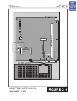
The DS 616 system consists of the Basic Key Service Unit (KSU), option boards, trunk
interface cards, interface modules, and digital keysets. The KSU is a single metal
cabinet with a basic configuration of 16 station ports: twelve (12) keyset ports and four
(4) SLT (Single Line Telephone) ports.
The Basic Key Service Unit (KSU) contains one Trunk Expansion slot, for installing the
3 TRK or 6 TRK PCB. Two option card connectors, for installing the Serial Interface card
and the optional AA card.
The KSU also contains one (1) External Page Interface, one (1) General Purpose Dry
contact and one (1) Music Interface selection switch, for selecting the Internal Music
Source (melody chip) or an External Music Source.
The trunk expansion slot has the provision for installation for an analog trunk card.
Trunk capacities of 3 and 6 exchange lines respectively are achieved by installing the 3
TRK card or 6 TRK cards.
The SIO2 card provides 2 serial ports (2RS232C) for connection to a PC, printer or
modem, and an 8 channel CID signal decoder (for analog Caller ID).
The AA option board is equipped with a 4 channel Auto Attendant.
Two types of telephones can be connected to the system: proprietary digital stations—
DS 24D keysets that connect to DLI (Digital Line Interface) ports, and standard
telephone sets—Single Line Telephones that connect to SLI (Single Line Interface)
ports.
HOME
PAGE
Table of
Contents


