background image

COLOR TELEVISION RECEIVER

Chassis : 

KS1A(P)

Model   :

CZ20F12TSXVXEH

COLOR TELEVISION RECEIVER

CONTENTS

Precautions

Specifications and IC Data

Disassembly and Reassembly

Alignment and Adjustment 

Troubleshooting

Exploded View and Parts List

Electrical Parts List

Block Diagram

Wiring Diagram

Schematic Diagrams

1.

2.

3.

4.

5.

6.

7.

8.

9.

10.

RTV servis Horvat 

Tel:       ++385-31-856-842
Tel/fax: ++385-31-856-139 
Mob:         098-788-319 

 www.rtv-horvat-dj.hr 

www.rtv-horvat-dj.hr

www.rtv-horvat-dj.hr

Summary of Contents for CZ20F12TSXVXEH

Page 1: ... Data Disassembly and Reassembly Alignment and Adjustment Troubleshooting Exploded View and Parts List Electrical Parts List Block Diagram Wiring Diagram Schematic Diagrams 1 2 3 4 5 6 7 8 9 10 RTV servis Horvat Tel 385 31 856 842 Tel fax 385 31 856 139 Mob 098 788 319 www rtv horvat dj hr www rtv horvat dj hr www rtv horvat dj hr ...

Page 2: ...binets screwheads and control shafts The current measured should not exceed 0 5 milliamp Reverse the power plug prongs in the AC outlet and repeat the test Fig 1 1 AC Leakage Test 6 Antenna Cold Check With the unit s AC plug disconnected from the AC source connect an electrical jumper across the two AC prongs Connect one lead of the ohmmeter to an AC prong Connect the other lead to the coaxial con...

Page 3: ...heated or that are otherwise damaged should be replaced with parts that meet the original specifications Always determine the cause of damage or overheat ing and correct any potential hazards 15 Observe the original lead dress especially near the following areas Antenna wiring sharp edges and especially the AC and high voltage power supplies Always inspect for pinched out of place or frayed wiring...

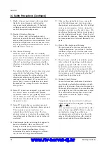
Page 4: ...uctive parts examples metal panels input terminals and earphone jacks 6 Insulation Checking Procedure Disconnect the power cord from the AC source and turn the power switch ON Connect an insulation resistance meter 500V to the blades of the AC plug The insulation resistance between each blade of the AC plug and accessible conductive parts see above should be greater than 1 megohm 7 Never defeat an...

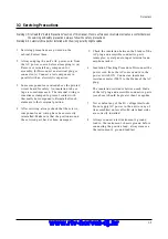
Page 5: ...amage ESDs 5 Use only a grounded tip soldering iron when soldering or unsoldering ESDs 6 Use only an anti static solder removal device Many solder removal devices are not rated as anti static these can accumulate sufficient electrical charge to damage ESDs 7 Do not remove a replacement ESD from its protective package until you are ready to install it Most replacement ESDs are packaged with leads t...

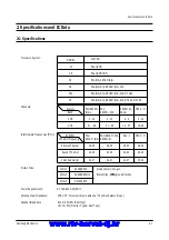
Page 6: ...IF Carrier Color Sub Carrier PAL SECAM D K 1 13 21 69 PAL SECAM D K SECAM K1 38 90 32 40 34 47 SECAM K1 PAL D 2 9 13 57 PAL I 38 90 32 90 34 47 MODEL CI CII CX CK CW CS 14 Inch 20 Inch 21 Inch AC 100 240V 50 60Hz VHF UHF Telescopic dipole antenna 75 ohm unbalanced type 8 ohm 5W 5W Dual Type 16 ohm 3W Monitor Type Dual Type SYSTEM PAL I UHF PAL I VHF UHF PAL B G SECAM B G PAL B G D K SECAM B G D K ...

Page 7: ...PLER SPM802ER TTX English Croatian Romanian Hungarian Polish Czech Bulgarian Russian Portugal IC201S Philips Philips SPM802ERN W O TTX English Croatian Romanian Hungarian Polish Czech Bulgarian Russian Portugal VERTICAL OUTPUT LA7840 TDA7266S IC301 IC601 SOUND AMP 3W x 1CH or 3W x 2CH or 5W x 2CH IC801S KA5Q0765R POWER IC STR IC802 KA7632 CUSTOM REGULATOR 5V 8V 3 3V IC101 U4468B SIF IC TEMIC Sanyo...

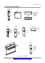
Page 8: ...24CO8P Pin 8 KS24C080 Pin 8 U4468B Pin 16 IC TRANSISTOR LA7840 TDA6107Q KA7632 TRANSISTOR TRANSISTOR 2SD1651 2SD1650 2SD2499 KSA614 B C E E B C KSC815 Y KSA539 Y BC548 KTC9014 IC UPC574J or KA33V SAW FILTER E C B KSR1012 KSR1010 KSR2010 KTD863 Y KSC2331 Y 1 1 1 G3956M K9260M Fig 2 1 Semiconductor Base Diagrams www rtv horvat dj hr www rtv horvat dj hr ...

Page 9: ...nd reassembly 3 Disassembly and Reassembly 3 1 Back Cover Removal 1 After removing the screws press the tension rib and pull the cabinet backwards 2 To reassemble press the tension rib see diagram www rtv horvat dj hr www rtv horvat dj hr ...

Page 10: ...oard from the CRT neck 2 Remove the Anode Cap from the CRT 3 Remove the main board by pulling it with both hands Warning The FBT is charged with high voltage Before removing the Anode Cap discharge the voltage through one of the heat sinks on the main board www rtv horvat dj hr www rtv horvat dj hr ...

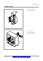
Page 11: ...moval Disassembly and reassembly Samsung Electronics 3 3 1 Remove the speaker by pressing the tension rib 1 Remove the screws 2 Remove the speaker by pressing the tension rib www rtv horvat dj hr www rtv horvat dj hr ...

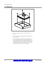
Page 12: ...net Lift the CRT 3 Caution Because of the high vacuum and large surface area of the picture tube be careful while handling it 1 Always lift the picture tube by grasping it firmly around the faceplate 2 Never lift the tube by its neck 3 Do not scratch the picture tube or apply excessive pressure Fractures of the glass may cause an implosion www rtv horvat dj hr www rtv horvat dj hr ...

Page 13: ... the EEPROM or CRT is replaced set PVA to 40 factory mode and set SC as follows 14 inch 0 20 inch 9 21 inch 9 4 2 Factory Service Mode 4 2 1 Procedure for the Adjustment Mode 1 This mode uses the standard remote control The Service Mode is activated by entering the following remote control sequence 1 DISPLAY FACTORY 2 STAND BY DISPLAY MENU MUTE POWER ON 2 The SERVICE FACTORY message will be displa...

Page 14: ...3 VS Ver t i cal Shi f t 0 63 VA Ver t i cal Am pl i tud e 0 63 HS Hor i zont al Shi f t 0 63 SC S Cor r ec t i on 0 63 CDL Cat hode Dri ve Level 0 15 STT Sub Ti nt 0 7 SSP Sub Sharpnes s 0 7 PDL PAL Del ay 0 15 NDL NTSC Del ay 0 15 PSR PAL Sub c ol oR 0 23 NSR N TSC Sub c ol oR 0 23 AGC Autom at i c Gai n Cont r ol 0 63 VOL Vol ume pre s et t i ng 0 63 L CO SECAM L V i s i on I F 0 1 TXP TTX Pos ...

Page 15: ...In the Service Mode various can be selected via the Option Table Example 1 2 3 4 5 6 7 8 9 10 Option Table xx xx xx xx LNA SYSTEM AUDIO JACK ZOOM AUTO POWER SBL 2nd SIF HOTEL MODE BKS ON CZ MONO RCA NOR ZOOM 16 9 ON OFF ON OFF ON www rtv horvat dj hr www rtv horvat dj hr ...

Page 16: ... is disconnected before replacing any parts 8 To protect against shock hazard use an isola tion transformer 4 3 2 Automatic Degaussing A degaussing coil is mounted around the pic ture tube so that external degaussing after moving the TV should be unnecessary But the receiver must be properly degaussed upon installation The degaussing coil operates for about 1 sec ond after the power is switched ON...

Page 17: ...e pattern Use a pattern gen erator PM5518 3 Use the P mode key on the remote control for the STANDARD picture 4 Adjust the Screen VR on the FBT so that the voltage on the oscilloscope becomes 120 2 5V See Fig 4 1 4 3 6 Purity Adjustment 1 Warm up the receiver for at least 20 minutes 2 Plug in the CRT deflection yoke and tighten the clamp screw 3 Plug the convergence yoke into the CRT and set in as...

Page 18: ...n Belt Fig 4 4 1 2 a Set up 1 Warm up the TV for at least 30 minutes in the Aging Mode OSD White This mode is dis played by entering the following sequence DISPLAY FACTORY FACTORY 2 Input a Toshiba pattern b Low Light Adjustment 1 Set SBT to 3 5 0 5 fL in the Factory Service Mode with using CA100 See Fig 4 4 2 Adjust RG BG so that the levels are suitable to each local area c High Light Adjustment ...

Page 19: ... lines in the center area of the screen 5 Turn the both tabs at the same time keeping the angle constant and superimpose the red and blue horizontal line in the center of the screen 6 Adjust the two tab pairs of the 6 pole magnets to superimpose the red and blue line onto the green Changing the angle affects the vertical lines and rotating both magnets affects the horizontal lines 7 Repeat adjustm...

Page 20: ...rcle becomes oval 3 Adjust with VSL Vertical Slope so that the bottom margin of the picture is 4 Fig 4 7 4 Adjust with VS Vertical shift so that the top margin of the picture is 4 Fig 4 8 5 Adjust with HS Horizontal Shift so that the lion head pattern and CRT centers are aligned Fig 4 9 6 Adjust HS using the width coil so that the left and right margins of the picture are 5 Alignment and Adjustmen...

Page 21: ...pen the IF Pin of Tuner Check Replace TU01S No Measure the Voltage of Each Pin of TU01S Check IC201S Pins 2 3 See No Video Sound OK See No Sound Video OK Check Replace IC201S Yes No Check Replace IC501 IC201S Check IC201S Pins 40 49 50 See No Sound Video OK www rtv horvat dj hr www rtv horvat dj hr ...

Page 22: ...in 8 8V Pin 9 9V Pin 10 5V Check Replace IC801S D801S D802S D803S D804S FP801S Check Replace IC802 KA7632 Check IC201S Pin 1 Stand by 0V Normal 3 3V Check Replace IC201S Check IC201S Pin 1 3 3V Check Replace IC201S µ com Check IC201S Pin 33 H out Check Replace IC201S Q401 Q402 www rtv horvat dj hr www rtv horvat dj hr ...

Page 23: ...n 40 CVBS Check Replace IC201S Check IC201S Pins 38 R214 R215 Check IC201S Pin 49 V GUARD Pin 50 Cut off Pin 51 53 R G B out Check Replace IC201S Check IC501 on the CRT PCB Check Replace IC501 Check Replace R421 R505 HEATER 6 3Vrms D503 CRT G1 pin CRT V999S www rtv horvat dj hr www rtv horvat dj hr ...

Page 24: ...ck IC201S Pin 44 Sound Out Check Replace IC201S Check IC601 Pin 3 13 B 10 12 5V Check Replace Q904 IC201S Check IC601 Check Replace IC601 Check IC601 Pins 6 0V Check Replace R814 R815 Yes Yes No Yes Yes 5 5 No TTX No See No Video Check IC201S Check Replace IC201S Yes www rtv horvat dj hr www rtv horvat dj hr ...

Page 25: ...8 AA64 02599A KNOB CONTROL 20F1 21F1 HIPS HB SV 012P I 1 1 9 6002 000515 SCREW TAPPING RH 2 M4 L15 ZPC SWRCH18 1 KC CF 1 10 AA96 00853A ASSY SPEAKER 16OHM 3W 3001 001039 700 1 1 11 6002 000515 SCREW TAPPING RH 2 M4 L15 ZPC SWRCH18 2 SPK CF 2 AA94 05858A ASSY CRT A48KRD82X01 H 380MG 20 1 2 1 AA65 30107A CLAMP D COIL 20 22 INCH NYLON 66 V2 NT 4 2 2 AA60 10050Q SCREW ASSY SWRCH18A M5 L26 5 HH WC 4 CR...

Page 26: ...CARBON 15KOHM 5 1 8W AA TP 1 8X3 2MM 2 R602 2001 000008 R CARBON 15KOHM 5 1 8W AA TP 1 8X3 2MM 2 R205 2001 000011 R CARBON 75Kohm 5 1 8W AA TP 1 8x3 2mm 2 R301 2001 000016 R CARBON S 1OHM 5 1 2W AA TP 2 4x6 4MM 2 J125 2001 000016 R CARBON S 1OHM 5 1 2W AA TP 2 4x6 4MM 2 R843 2001 000019 R CARBON S 10OHM 5 1 2W AA TP 2 4X6 4M 2 R618 2001 000019 R CARBON S 10OHM 5 1 2W AA TP 2 4X6 4M 2 R409 2001 000...

Page 27: ... TP 6 5x3 0x5 5mm 2 C217 2301 000342 C FILM PEF 2 2nF 5 50V TP 7 4x3 9x13mm 2 C234 2301 000342 C FILM PEF 2 2nF 5 50V TP 7 4x3 9x13mm 2 C407 2301 000383 C FILM PEF 10nF 5 50V TP 6x7x3 2mm 5mm 2 C227 2301 000445 C FILM PEF 4 7nF 5 50V TP 5 5x7x3mm 5mm 2 C248 2301 000445 C FILM PEF 4 7nF 5 50V TP 5 5x7x3mm 5mm 2 C420 2301 001065 C FILM MPPF 47nF 5 630V TP 19x15 5x7 7 2 C301 2305 000285 C FILM MPEF 2...

Page 28: ...J176 3812 000219 WIRE NO SHEATH CU TCWA 300V 52mm TAPING 2 J182 3812 000219 WIRE NO SHEATH CU TCWA 300V 52mm TAPING 2 J185 3812 000219 WIRE NO SHEATH CU TCWA 300V 52mm TAPING 2 J186 3812 000219 WIRE NO SHEATH CU TCWA 300V 52mm TAPING 2 J187 3812 000219 WIRE NO SHEATH CU TCWA 300V 52mm TAPING 2 J189 3812 000219 WIRE NO SHEATH CU TCWA 300V 52mm TAPING 2 J190 3812 000219 WIRE NO SHEATH CU TCWA 300V 5...

Page 29: ...MIC MLC AXIAL 4 7nF 20 16V Y5R TP 2 R302 2004 001369 R METAL S 1 2Kohm 1 1 2W AA TP 2 4x6 4 2 D804 0401 000006 DIODE SWITCHING BAV21 250V 250mA DO 35 T 2 D805 0402 001470 DIODE RECTIFIER RU2BV1 800V 1A DO 204AC 2 R808 2001 001138 R CARBON S 390OHM 5 1 2W AA TP 2 4X6 4 2 R831 2001 001088 R CARBON S 1KOHM 5 1 2W AA TP 2 4X6 4M 2 R405 2001 001116 R CARBON S 27OHM 5 1 2W AA TP 2 4X6 4M 2 C203 2401 002...

Page 30: ...TE TPC180 3 HA83 00006A LP RESIN HIPS BASF495F NTR HB 3 HA83 00011A LP RESIN M BATCH WILSON 6007 GY 60 GRY 2 AA96 00853A ASSY SPEAKER 16OHM 3W 3001 001039 700 3 3001 001039 SPEAKER 3W 16ohm 90dB 180Hz 3 AA39 20500C LEAD CONNECTOR ASSY 3 2 67096 003 REC ASSY CABINET COM 1 AA90 01062A ASSY CABINET COM 20F1 2 CB CF 6002 000515 SCREW TAPPING RH 2 M4 L15 ZPC SWRCH18 2 CRT CF AA60 10050Q SCREW ASSY SWRC...

Page 31: ...3V TO MCU 8V TO MCU I 2C AUDIO A M P TDA 7266S FBT 14 20 21 FSV 14 A 004C S VIDEO AUDIO I 2C VIDEO SI F SA W K9260M U4468B AUDIO IC M C U SP M 802X X X 2 3 2 4 32 21 22 50 53 44 28 2 3 45 48 38 42 35 2 12 8 S W 2 S W 1 11 P r e A M P PAP103T SYSTEM OPTION R G B FB H OUT TR 3 3 16 5V TO Ver A M P 180V TO C RT Heat TO C RT 13V TO SOUND AMP 8R 2E A 16R 2E A 16R 1E A 8R 1E A KA7632 2SD 2499 Option Q w...

Page 32: ...N SOUND R IN FRONT AUDIO IN GND 21 PIN AUDIO IN GND CRT PCB POWER CORD 1 2 3 4 5 180V GND CUT OFF B OUT G OUT R OUT HEAT NC 1 2 3 GND HEAT 180V 1 2 3 4 L OUT R OUT L OUT R OUT CN501B CN501 CN603 CN701 9 10 11 SOUND R OUT GND FRONT VIDEO IN 21 PIN VIDEO IN 6 7 8 www rtv horvat dj hr www rtv horvat dj hr ...

Page 33: ...4 TP09 TP08 TP10 TP11 TP13 TP12 Schematic Diagrams 10 1 Samsung Electronics 10 Schematic Diagrams 10 1 ONECHIP MICOM Power Line TP01 TP02 TP04 TP05 TP07 TP08 TP10 TP11 TP13 TP14 TP03 TP06 TP09 TP12 www rtv horvat dj hr www rtv horvat dj hr ...

Page 34: ...Schematic Diagrams 10 2 Samsung Electronics 10 2 SOUND EXT A V RCA TP01 TP02 21 PIN BUS 21 PIN BUS TP01 TP02 Power Line www rtv horvat dj hr www rtv horvat dj hr ...

Page 35: ...Schematic Diagrams 10 3 Samsung Electronics 10 3 SOUND EXT A V SCART TP01 TP02 B BUS B BUS TP01 TP02 Power Line www rtv horvat dj hr www rtv horvat dj hr ...

Page 36: ...Schematic Diagrams 10 4 Samsung Electronics TP06 TP01 TP02 TP04 TP03 TP05 10 4 POWER CRT VERTICAL HORIZONTAL TP01 TP02 TP03 TP04 TP05 TP06 Power Line www rtv horvat dj hr www rtv horvat dj hr ...

Reviews: