Confidential
3
.
Installing the Product
English 8/2019. Rev 0.0
23
3.5
Preparation Stage—Unpacking
Check the following parts during unpacking:
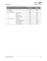
Table 3-2: Parts for 136S 3P Rack
No.
Items
Part No.
Amount
(Unit: EA)
Remarks
1
RACK FRAME
V808-00066A
V808-00068A
3
V808-00066A: White, for specific customer
V808-00068A: Black, for general customer
2
BATTERY MODULE Type A
EM2031AE00XA
24
X = 1 for specific customer
X = 3 for general customer
3
BATTERY MODULE Type B
EM2031AE00YA
27
Y = 2 for specific customer
Y = 4 for general customer
4
SMU
V049-0011XA
3
X = A for general customer
X = B for specific customer
5
SMPS ASSEMBLY Type A
(WITH SYSTEM BMS ASSEMBLY)
V044-0004AA (1 Phase)
V044-0006AA (3 phase)
1
For Rack #1
X = A for general customer
X = B for specific customer
6
SMPS ASSEMBLY Type B
V044-0005AA (1 phase)
SJ94-00238B (3 phase)
2
For Rack #2, 3
For general customer
7
BUSBAR M TO SMU
V050-00051A
6
Connect modules and SMU
8
BUS-BAR MAIN
SJ66-00863A
39
High current bus bar connection for modules
9
RACK FUSE BUSBAR_R_136S
SJ66-00868A
3
Connect between modules #8 and #9
10
RACK FUSE BUSBAR_L_136S
SJ66-00876A
3
Connect between modules #8 and #9
11
FUSE
3601-001835
9
Connect between modules #5 and #6, between modules #8 and #9,
and between modules #14 and #15
12
FUSE COVER #1
SJ63-00101A
3
Fuse cover for fuse between modules #8 and #9
13
FUSE COVER #2
V143-00002A
12
Fuse cover for fuse between modules #5 and #6, and between
modules #14 and #15
14
FUSE BUSBAR LEFT UPPER
V050-00002A
3
Connect between modules #14 and #15
15
FUSE BUSBAR LEFT LOWER
V050-00001A
3
Connect between modules #14 and #15
16
FUSE BUSBAR RIGHT UPPER
V050-00003A
3
Connect between modules #5 and #6
17
FUSE BUSBAR RIGHT LOWER
V050-00004A
3
Connect between modules #5 and #6
18
WIRE ASSY RACK TO MODULE
V046-0005BA
3
Connect Battery Module #1 and SMU.
19
WIRE ASSY MODULE TO MODULE #1
SJ39-00673A
45
Signal Connection for Modules
20
WIRE ASSY RACK TO RACK #2
SJ39-00674A
2
Connect Rack between #1, #2 and #3.
21
WIRE ASSY RACK TO SYSTEM
SJ39-00719A
1
Connect the Rack BMS CAN connector in the SMU to the System BMS
CAN connector in the SMPS ASSEMBLY.
22
WIRE ASSY RACK TO SMPS
SJ39-00718A
6
Connect the Rack BMS DC IN to SMPS ASSEMBLY DC OUT
23
WIRE ASSY MODULE TO MODULE #2
SJ39-00678A
3
Signal connection between modules #8 and #9
24
WIRE ASSY EARTH
SJ39-00725A
6
Connecting SMPS Assembly and SMU to Rack Frame.
25
SCREW M5 X 10
SJ60-00068A
30
Mounting SMU, SMPS, and WIRE ASSY EARTH to Rack Frame
26
SCREW M8 X 17
SJ60-00152A
102
Mounting Busbar to Module
27
SCREW M12 X 25
SJ60-00138A
12
Mounting Busbar to Switchgrear
28
SCREW M12 X 16
SJ60-00137A
18
Mounting Fuse Busbar to Fuse
29
SCREW M10 X 25
SJ60-00082A
12
Mounting Rack Frame to Rack Frame side by side
30
NUT M10
SJ81-01208A
12
Mounting Rack Frame to Rack Frame side by side
31
M10 FLAT WASHER
SJ60-00073A
12
Mounting Rack Frame to Rack Frame side by side
32
WIRE ASSY MCCB AUX
SJ39-00807A
3
Connect to MCCB Aux Contact
33
WIRE ASSY DRY CONTACT
SJ39-00808A
1
Connect to SMPS Assembly DRY CONTACT
Summary of Contents for 136S
Page 1: ...Confidential English 8 2019 Rev 0 0 LIB System for UPS Installation Manual 136S ...
Page 4: ...Confidential English 8 2019 Rev 0 0 ...
Page 10: ...Important Safety Instructions Confidential vi English 8 2019 Rev 0 0 ...
Page 18: ...Confidential Table of Contents viii English 8 2019 Rev 0 0 ...
Page 153: ...Confidential Memo ...
Page 154: ...Confidential Memo ...
Page 155: ...Confidential Memo ...
Page 156: ...www SamsungSDI com ...

