HA2500 2
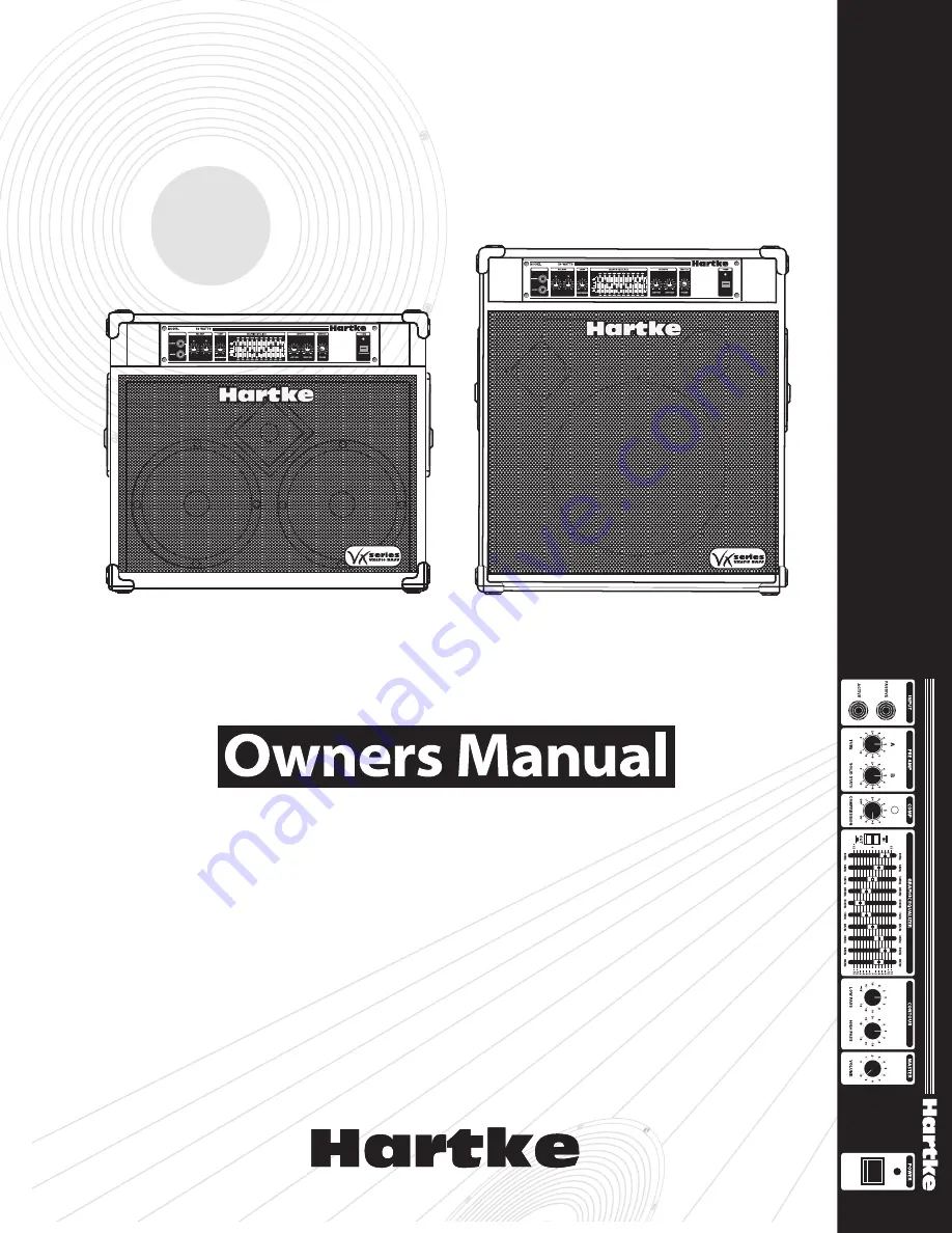
250 WATT 1 X 15” BASS COMBO
250 WATT 2 X 10” BASS COMBO
VX2515
VX2510
Page 1: ...HA2500 2 HA2500 2 250 WATT 1 X 15 BASS COMBO 250 WATT 2 X 10 BASS COMBO VX2515 VX2510 ...
Page 2: ......
Page 3: ...ession 12 Appendix A Caster Installation 13 Appendix B Block Diagram 14 Appendix C Changing the VX2510 VX2515 Voltage 15 Specifications 16 Copyright 2005 2008 Samson Technologies Corp Printed June 2008 v1 1 Samson Technologies Corp 45 Gilpin Avenue Hauppauge New York 11788 8816 Phone 1 800 3 SAMSON 1 800 372 6766 Fax 631 784 2201 www samsontech com ...
Page 4: ...struments and the front panel controls in both models are virtually identical You ll find either to be an excellent bass amplifier for live performance use in small and medium size venues in addition the VX2510 VX2515 s advanced pre amp features makes it ideal for use in recording environments In these pages you ll find a detailed description of the many features of the VX2510 VX2515 bass amplifie...
Page 5: ...tour knobs high pass and low pass which provide fur ther control over shaping your bass sound A built in compressor which not only adds real punch to your bass sound but also allows you to smooth out volume differences between notes Two independent inputs that accommodate both passive and active bass gui tars Protection relay circuitry that protects connected speakers from dangerous over loading a...
Page 6: ... sound of a classic tube amplifier Note that when both Pre Amp knobs are used at equal settings the amplifier will be twice as loud as when only one is used Avoid setting both Pre Amp knobs on maximum 10 since the result will almost always be undesirable distortion 4 Pre Amp B Solid State control This determines the amount of pream plification being provided by special circuitry which delivers the...
Page 7: ...0 position the selected frequency area is unaffected it is said to be flat When a slider is moved up above the 0 position towards the 15 position the selected frequency area is boosted and when it is moved down below the 0 position towards the 15 position the selected frequency area is attenuated For more informa tion see the About Equalization section on pages 10 11 of this manual 8 Contour Low P...
Page 8: ...o change the voltage rating see Appendix B on page 14 2 AC input Connect the supplied standard 3 pin IEC plug here 3 Fan The fan provides vital cooling to your Model 2500 Make sure that it is kept free of all obstructions and that cool fresh air is accessible at all times Also try to ensure that the Model 2500 is used in a dust free environment 4 Effect Return jack Use this 1 4 unbalanced jack to ...
Page 9: ...ter Volume control You can also use the Effect Send jack to route signal to an external mixing console or amplifier with an input sensitivity of 4 dB 6 Speaker outputs The VX2510 VX2515 internal speaker system is connected here In line effects such as footpedals intended for low signal levels should be placed between the bass and the amplifier Input and not connected with the Effect Send and Retur...
Page 10: ... page 13 of this manual 3 Next connect the 3 pin AC plug into any grounded AC socket Don t turn the amplifier on just yet though 4 Use a standard music instrument cable to connect your bass to the appropri ate Input jack on the front panel if your bass has active circuitry connect it to the Active input if not connect it to the Passive input On the front panel of the Model VX2515 VX2510 set the Ma...
Page 11: ...n Out switch to its In position so that the graphic equalizer is acti vated Finally move each slider in turn as you play your bass For more informa tion see the About Equalization section on page 13 of this manual Again when you get a graphic equalization setting that complements your instrument and playing style it s a good idea to write it down for future use 10 Now try out the Model VX2515 VX25...
Page 12: ...s Contour control affects a broad band of frequen cies with 100 Hz as the center point similarly the High Pass Contour control affects a broad band of frequencies with 10 kHz as the center point When either is in its cen ter detented position 0 it is having no effect When it is moved right of center the particular frequency area is being boosted when it is moved left of center the fre quency area ...
Page 13: ...t boosting a frequency area also has the effect of boosting the overall signal specifically too much low frequency EQ boost can actually cause overload distortion or even harm a connected speaker though the Model 2500 s compression circuitry if on will act to some extent to prevent this from occur ring In general if you re going to apply a fair amount of low frequency EQ boost it s a good idea to ...
Page 14: ...provides a front panel Compression LED which acts as a useful visual indicator of the continuous activity of the compression circuitry When lit steadily green for example when the Compression knob is set to Off no compression is being applied When unlit compression is being applied to the incoming signal at a ratio of approximately 2 1 When flashing red the compression ratio is approach ing infini...
Page 15: ...shers Hold the caster in place and hand start the screws Be careful to ensure that the screws are on the proper thread chase DO NOT PUSH TEE NUT INTO ENCLOSURE Use a screw driver to tighten the four screws Be careful not to over tighten the screws Repeat the steps above for the remaining three casters ...
Page 16: ...14 Appendix B Block Diagram Model 2500 ...
Page 17: ...15 Appendix C Changing the VX2510 VX2515 Voltage ...
Page 18: ...2 1 to infinity Send Output Level 0 dBM Return Input Level 0 dBM VX2510 Speaker System Impedance Ohms 4 Ohms Impedance Low Frequency Drivers 2 10 Special Design 8 ohm 150 watt Speakers High Frequency Driver 1 Throat Compression Driver VX2515 Speaker System Impedance Ohms 4 Ohms Impedance Low Frequency Drivers 1 15 Special Design 4 ohm 250 watt Speakers High Frequency Driver 1 Throat Compression Dr...
Page 19: ......
Page 20: ...Hartke 45 Gilpin Avenue Hauppauge New York 11788 8816 Phone 1 800 3 SAMSON 1 800 372 6766 Fax 631 784 2201 www hartke com ...