Automation System TROVIS 5100
Ventilation Controller
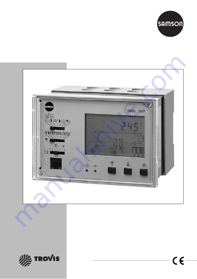
TROVIS 5177
Mounting and
Operating Instructions
EB 5177 EN
®
Electronics from SAMSON
Firmware version 1.05Edition September 2000
Page 1: ...Automation System TROVIS 5100 Ventilation Controller TROVIS 5177 Mounting and Operating Instructions EB 5177 EN Electronics from SAMSON Firmware version 1 05 Edition September 2000 ...
Page 2: ...ode 30 3 3 6 Configuration levels Co and function blocks Fb 31 4 Description of systems 34 5 Function descriptions 48 5 1 Control method 48 5 1 1 Supply air temperature control 48 5 1 2 Exhaust air temperature control 48 5 1 3 Exhaust air temperature cascade control 49 5 1 4 Room temperature control 50 5 1 5 Room temperature cascade control 50 5 1 6 Supply air humidity control 51 5 1 7 Exhaust air...
Page 3: ...21 Y4 65 5 3 17 Request for externally required signal over LON Co1Fb01 66 5 4 Time functions 68 5 4 1 Summer deactivation 68 5 4 2 Summer time operation PA 68 5 4 3 Automatic summer time winter time changeover Co5Fb16 69 5 4 4 Public holidays and vacations PA5 69 5 4 5 Time schedules times of use PA4 PA5 69 5 5 Control functions 70 5 5 1 System start up mode 70 5 5 2 Summer compensation PA5 71 5 ...
Page 4: ...ing the interface 86 8 Memory module 87 8 1 Data transfer between controller and memory module 87 9 Installation 88 10 Electrical connection 90 11 Technical data 93 Appendix A Lists of function blocks 95 Appendix A 1 Configuration level Co1 for heating coil 95 Appendix A 2 Configuration level Co2 for heat recovery 95 Appendix A 3 Configuration level Co3 for cooling coil 95 Appendix A 4 Configurati...
Page 5: ...Parameters set in PA7 level LON communication 120 Appendix B 7 Parameter der Ebene PA9 Modbus 121 Appendix C Operating level 124 Appendix C 1 Info level InF1 124 Appendix C 2 Info level InF2 125 Appendix C 3 Info level InF3 126 Appendix C 4 Info level InF4 127 Appendix C 5 Info level InF5 128 Appendix D Resistance values of temperature sensors 129 Appendix E Customer data 131 Index 142 Key code 14...
Page 6: ...ed to the power supply it is basically ready for opera tion Since the controller functions according to time schedules make sure the time and date are set before start up Refer to page 22 onwards for step by step instructions on how to set the time and date The controller also saves information on con figuration and parameters in a memory that can function for a long time without a power supply On...
Page 7: ... that are vital for the system are monitored Safety features such as frost protection monitoring and excess temperature protection however are not active in the following cases de fective controller and failure of function defective sensors or sensors that are not connected or have not been deactivated lack of operating voltage to the controller 4 The installation and electrical wiring de scribed ...
Page 8: ...ntrols on front panel 3 1 1 Mode switch A Use this switch to select the operating mode Automatic operation Rated opera tion stand by operation The control ler works according to set times of use and switches between rated and stand by operation Automatic operation Rated opera tion reduced operation The control ler works according to set times of use and switches between rated and in contrast to pr...
Page 9: ...mp s Fans former symbol 3 1 3 Changeover key and reset key C D Theses keys must be operated with a pointed object e g pencil The following functions are available Changeover key lets you change between the main levels operating and configuration levels Reset key resets all parameters in the parameter level to their default settings 3 1 4 Set point correction switch F The set point can be increased...
Page 10: ...b solute control and takes on responsibility for interaction between all the outputs and the resulting consequences As soon as you set the mode switch to the switch position all operating states of the controller outputs are frozen i e the con trol signals as well as the switching states of the binary outputs from automatic operation are kept regardless of the input variables If you have changed t...
Page 11: ...he selec tion switch for manual opera tion B to the output that you want to change Y1 Control signal Y1 Y2 Control signal Y2 Y3 Control signal Y3 Y4 Control signal Y4 Pump s Fans The associated symbol blinks on the display Note appears when this output is not connected 24 M Y1 M M Y3 Y1 Y2 Y3 23 22 21 20 19 18 17 16 15 14 13 12 11 10 9 8 7 6 5 4 2 1 0 3 24 M Y1 M M Y3 Y1 Y2 Y3 23 22 21 20 19 18 17...
Page 12: ...g with Anl 3 use the enter key to select another pump The symbol of the selected pump blinks on the display when the pump is switched off just the circuit blinks Any changes to an output are kept if you push the selection switch for manual operation B Slide Display shows Comments the mode switch A to 24 M Y1 M M Y3 Y1 Y2 Y3 23 22 21 20 19 18 17 16 15 14 13 12 11 10 9 8 7 6 5 4 2 1 0 3 24 M Y1 M Y1...
Page 13: ...cord ing to the level All other indices are summa rized in the table opposite Usually the ventilation controller is in the operating level and the time appears on the display In Fig 1 for example 10 24 is indicated on the display Apart from the time symbols to represent the operating mode and operating status as well as the sys tem represented symbolically appear on the display Refer to page 147 f...
Page 14: ...Sensor initialization LON communication LON communication Heating coil Information on Information on Function block setting for Parameters for Heating coil Heat recovery mixed air chamber Heat recovery mixed air chamber Heating coil Heat recovery mixed air chamber Cooling coil Cooling coil Cooling coil InF1 InF2 InF3 PA1 Co9 Co8 Co7 Co6 Co5 PA2 PA3 PA4 PA5 PA7 PA9 Co4 Anl Time Operating level Conf...
Page 15: ...t is not possible to make any changes to parameters when the controller is in an info level Activating the info level from the operating level 14 EB 5177 EN Operation Control levels Press Display shows Comments or Use arrow keys to find the required InF level InF1 to InF5 Press enter key to activate the info level The first piece of information appears on the display This exam ple shows the supply...
Page 16: ...s on the display Press Display shows Comments both Any display Press both arrow keys simulta neously The next info level appears on the display depending on the sys tem code number or When End appears on the display press the enter key In this way you can also access the next info level 24 Y1 Y2 Y3 23 22 21 20 19 18 17 16 15 14 13 12 11 10 9 8 7 6 5 4 2 1 0 3 M Y1 M M Y3 24 Y1 Y2 Y3 23 22 21 20 19...
Page 17: ...ust air control causes the assignment of sensors to be reprogrammed the sensor inputs required for the function blocks are activated and the sensor inputs not used are deactivated These settings can be changed manually Proceed as follows to change the system code number 16 EB 5177 EN Operation Control levels Press Display shows Comments Press changeover key The parame ter level PA1 appears on the ...
Page 18: ... two arrows to indicate the control method This example shows supply air control or Use the arrow keys to select a differ ent control method Each control method is shown by the arrows on the right hand side in supply air duct exhaust air duct or both in the room or in the room and supply air duct this example shows room control 24 M Y1 M Y1 Y2 Y3 23 22 21 20 19 18 17 16 15 14 13 12 11 10 9 8 7 6 5...
Page 19: ...idifier control circuit now appears on the display The cooling coil and humidifier blink Set the con trol method in the same way as described for the temperature control cir cuit When selecting using the arrow keys a difference is made between humidifying and dehumidifying operation mode or just humidifying opera tion mode When the latter applies just the humidifier blinks on the display 24 M Y1 M...
Page 20: ...the display For the humidity control circuit the cooling coil and humidifier blink on the display Additionally for the humidity control circuit a difference is made between humidifying and dehumidifying operation and just humidifier operation You can set the control method in the configu ration level under the system code number Anl Refer to Changing the system code number in section 3 3 2 on page...