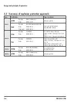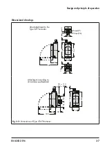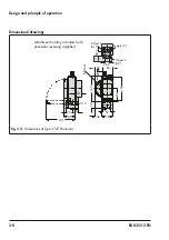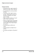
5-6
EB 8355-2 EN
Installation
The old connection block version requires
the switch plate (13) to be turned to align
the actuator symbol with the arrow mark-
ing.
8. Place the connection block with the asso-
ciated gaskets against the positioner and
the actuator yoke. Fasten it using the
screw.
For actuators with fail-safe action "actua-
tor stem retracts", additionally mount the
external signal pressure pipe.
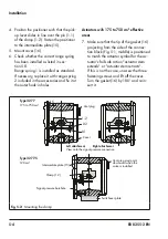
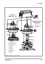
Actuator (120 cm²)
The signal pressure is transmitted to the dia-
phragm chamber over the switchover plate
(
, bottom).
7.
Remove screw plug on the back of the
positioner (
) and seal the side
signal pressure output with the stopper
included in the accessories.
8. Mount the positioner so that the hole in
the intermediate plate (15) covers the
seal in the hole of the actuator yoke.
9. Align the switchover plate with the corre-
sponding actuator symbol. Fasten it to
the actuator yoke.
If a solenoid valve or a similar device is ad-
ditionally mounted onto a 120 cm² actuator,
do not remove the M3 screw plug at the
back of positioner. In this case, the signal
pressure must be transmitted from the signal
pressure output to the actuator over an addi-
tional connecting plate (Table 5-5). The swi
-
tchover plate is not used in this case.
Air purging of the spring chamber
If the spring chamber of the actuator is to be
purged with the exhaust air from the posi-
tioner, use piping (
) to connect the spring
chamber (with "actuator stem extends" ver-
sion) to the connection block. To do so, re-
move the stopper from the connection block.
For an actuator with fail-safe action "actua-
tor stem retracts" and in Type 3277-5 Actua
-
tors with an effective diaphragm area of
120 cm², the exhaust air from the positioner
is connected to the actuator chamber over
an internal hole.
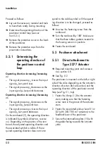
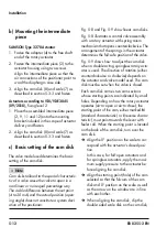
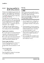
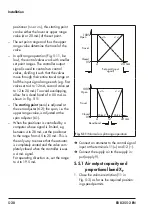
Spring
Screw plug
Fig. 5-4:
Installing the spring on the back of
the housing
5.3.2
Attachment according to
IEC 60534-6
The rated travel of the valve determines
which lever and range spring (see Table 5-1)
are required.
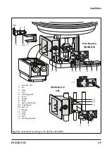
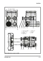
An adapter housing is used for attachment
(
). The valve travel is transmitted by
the lever (1) and the shaft (8) to the bracket
(11) of the adapter housing and then passed
on to the pin (10a) on the lever of the posi-
tioner. To ensure that the pin (10a) is proper-
Note
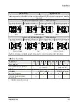
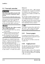
Left attachment
Right attachment
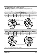
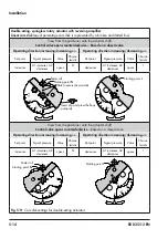
Mounting position on the plate looking onto the travel pick-off (20), actuator facing upward (see also
Actuator with “actuator stem extends” (FA) fail-safe action
Operating direction >> Operating direction <> Operating direction >> Operating direction <>
20
Output and supply
Input
Input
Actuator with “actuator stem retracts” (FE) fail-safe action
Operating direction >> Operating direction <> Operating direction >> Operating direction <>
20
Output and supply
Output and supply
Input
Fig. 5-5:
Attachment to the left or right of the valve for NAMUR attachment (IEC 60534-6)
Table 5-1:
Travel table
Travel [mm]
1)
7.5
15
15
30
30
60
30
60
60
120
Pin at marking
1)
1
2
1
2
1
2
1
2
1
2
Distance between pin and lever
fulcrum
42 to 84 mm
84 to 168 mm
With lever
N1 (125 mm long)
N2 (212 mm long)
Pin (27a) at position
A
A
B
A
B
Required range spring (see
section
2
1
1
1
1
1)
Calculate intermediate values
Summary of Contents for 3767
Page 10: ...1 6 EB 8355 2 EN...
Page 14: ...2 4 EB 8355 2 EN...
Page 58: ...6 2 EB 8355 2 EN...
Page 60: ...7 2 EB 8355 2 EN...
Page 70: ...10 2 EB 8355 2 EN...
Page 72: ...11 2 EB 8355 2 EN...
Page 74: ...12 2 EB 8355 2 EN...
Page 76: ...13 2 EB 8355 2 EN...
Page 78: ...14 2 EB 8355 2 EN...
Page 79: ...EB 8355 2 EN 14 3...
Page 80: ...14 4 EB 8355 2 EN...
Page 81: ...EB 8355 2 EN 14 5...
Page 88: ...14 12 EB 8355 2 EN...
Page 89: ...EB 8355 2 EN 14 13...
Page 90: ...14 14 EB 8355 2 EN...
Page 91: ...EB 8355 2 EN 14 15...
Page 92: ...14 16 EB 8355 2 EN...
Page 93: ...EB 8355 2 EN 14 17...
Page 94: ...14 18 EB 8355 2 EN...
Page 95: ...EB 8355 2 EN 14 19...
Page 96: ...14 20 EB 8355 2 EN...
Page 97: ...EB 8355 2 EN 14 21...
Page 98: ...14 22 EB 8355 2 EN...
Page 99: ...EB 8355 2 EN 14 23...
Page 100: ...14 24 EB 8355 2 EN...
Page 101: ...EB 8355 2 EN 14 25...
Page 102: ...14 26 EB 8355 2 EN...
Page 103: ...EB 8355 2 EN 14 27...
Page 104: ...14 28 EB 8355 2 EN...
Page 109: ......
Page 110: ...2 EB 8355 2 EN...
Page 111: ...EB 8355 2 EN 3...

