5-2
EB 8355-2 EN
Installation
Proceed as follows:
Î
Lay out the necessary material and tools
to have them ready during mounting.
Î
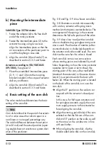
Determine the operating direction of the
positioner control loop (see sec-
tion
5.2.1).
Î
Remove the protective cover on the back
of the positioner.
Î
Remove the protective caps from the
pneumatic connections.
5.2.1
Determining the
operating direction of
the positioner control
loop
Operating direction increasing/increasing
<<
−
The signal pressure p
st
rises as the input
signal p
e
(set point) rises
−
The signal pressure p
st
decreases as the
input signal p
e
(set point) decreases
Operating direction increasing/decreasing
<>
−
The signal pressure p
st
decreases as the
input signal p
e
(set point) rises
−
The signal pressure p
st
rises as the input
signal p
e
(set point) decreases
On the turnboard (7), the operating direction
is indicated by symbols (direct
<<
, reverse
<>). Depending on the position of the turn
-
board, the adjusted operating direction and
the associated symbol is visible. If the re-
quired operating direction does not corre-
spond to the visible symbol or if the operat-
ing direction is to be changed, proceed as
follows:
Î
Unscrew the fastening screw from the
turnboard.
Î
Turn the turnboard by 180°. Make sure
that the three rubber gaskets inserted in
the housing remain in position.
Î
Fasten the turnboard.
5.3
Positioner attachment
5.3.1
Direct attachment to
Type 3277 Actuator
Î
Required mounting parts and accesso-
ries: section
Î
See
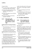
The positioner is mounted on the left or right
side of the valve depending on the actuator's
direction of action (fail-safe action) and the
operating direction of the positioner control
loop (see
, top).
1. Fasten the clamp (1.2) to the actuator
stem, making sure that the fastening
screw rests in the groove of the actuator
stem.
2. Fasten the associated pick-up lever D1 or
D2 (with 355/700 cm² actuators) to the
feedback lever of the positioner.
3. Secure the intermediate plate (15) with
the gasket facing towards the actuator
yoke.
SUPPL
Y
Actuator stem extends
Actuator stem retracts
Internal signal pres-
sure connection
Side view of connection block
Signal pressure
connection over piping
Connection block
Tip of gasket (16)
Operating
direction >> Left
attachment
Operating
direction <> Left
attachment
With gasket
(new)
With switch plate
(old)
Switch plate (13)
Gasket (16)
Cover
Switchover plate
Signal pressure input
Signal pressure
input for left
attachment
Seal with
filter
With right
attachment
Marking
Marking
Symbol
Actuator stem extends
Actuator stem retracts
Operating
direction <> Right
attachment
Actuator stem extends
>> Operating direction <>
Left attachment
Right attachment
Actuator stem retracts
<> Operating direction >>
Left attachment
Right attachment
Operating
direction >> Right
attachment
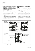
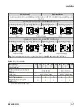
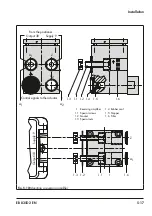
Fig. 5-1:
Mounting position and connection of signal pressure for Type 3277 Actuator (top) and
Type 3277-5 Actuator (120 cm²) (bottom)
Summary of Contents for 3767
Page 10: ...1 6 EB 8355 2 EN...
Page 14: ...2 4 EB 8355 2 EN...
Page 58: ...6 2 EB 8355 2 EN...
Page 60: ...7 2 EB 8355 2 EN...
Page 70: ...10 2 EB 8355 2 EN...
Page 72: ...11 2 EB 8355 2 EN...
Page 74: ...12 2 EB 8355 2 EN...
Page 76: ...13 2 EB 8355 2 EN...
Page 78: ...14 2 EB 8355 2 EN...
Page 79: ...EB 8355 2 EN 14 3...
Page 80: ...14 4 EB 8355 2 EN...
Page 81: ...EB 8355 2 EN 14 5...
Page 88: ...14 12 EB 8355 2 EN...
Page 89: ...EB 8355 2 EN 14 13...
Page 90: ...14 14 EB 8355 2 EN...
Page 91: ...EB 8355 2 EN 14 15...
Page 92: ...14 16 EB 8355 2 EN...
Page 93: ...EB 8355 2 EN 14 17...
Page 94: ...14 18 EB 8355 2 EN...
Page 95: ...EB 8355 2 EN 14 19...
Page 96: ...14 20 EB 8355 2 EN...
Page 97: ...EB 8355 2 EN 14 21...
Page 98: ...14 22 EB 8355 2 EN...
Page 99: ...EB 8355 2 EN 14 23...
Page 100: ...14 24 EB 8355 2 EN...
Page 101: ...EB 8355 2 EN 14 25...
Page 102: ...14 26 EB 8355 2 EN...
Page 103: ...EB 8355 2 EN 14 27...
Page 104: ...14 28 EB 8355 2 EN...
Page 109: ......
Page 110: ...2 EB 8355 2 EN...
Page 111: ...EB 8355 2 EN 3...

