background image

 10  

EB 8140 EN

Design and principle of operation

3  Design and principle of oper-

ation

The pneumatic control valve consists of a 
globe (straight-pattern) valve with a soft-
seated plug and a pneumatic piston 
actuator.

The medium flows through the valve in the 

direction indicated by the arrow. The signal 
pressure applied to the piston actuator deter-
mines the position of the plug and thus the 

cross-sectional area of flow between the seat 

and plug.
The plug/actuator stem (2) is sealed by a 
self-adjusting PTFE V-ring packing (4.4) at 

13

9

8

S

4.4

4.1

2

3

1

2

4.4

8

9

13

S

FE/NO

FA/NC

FE/NO

FA/NC

3

1

4.1

1

Body

2

Plug (with plug/actuator 

stem)

4.1 Radial shaft seal
4.4 Packing rings
8

Piston

9

Spring

13 Vent plug
S

Signal pressure connection

Fig. 2: 

Type 3354 Globe Valve · DN 15 to 50 (left) · DN 65 and 80 (right)

Summary of Contents for 3354

Page 1: ...Mounting and Operating Instructions EB 8140 EN Translation of original instructions Edition September 2017 Type 3354 Globe Valve...

Page 2: ...partment aftersalesservice samson de The mounting and operating instructions for the devices are included in the scope of delivery The latest documentation is available on our website www samson de Pr...

Page 3: ...Version FA NC with fail safe position fail close 13 3 4 2 Version FE NO with fail safe position fail open 14 3 5 Accessories 16 4 Measures for preparation 16 4 1 Unpacking 16 4 2 Transporting and lift...

Page 4: ...return shipment 31 7 5 Ordering spare parts and operating supplies 32 8 Malfunctions 33 8 1 Troubleshooting 33 8 2 Emergency action 34 9 Decommissioning and disassembly 35 9 1 Decommissioning 35 9 2...

Page 5: ...or for damage caused by external forces or any other external factors Refer to the technical data and nameplate for limits and fields of application as well as possible uses Reasonably foreseeable mis...

Page 6: ...opriate precautions They must observe all hazard statements warning and caution notes in these mounting and oper ating instructions especially for installation start up and service work We also recomm...

Page 7: ...d pipelines are pressure equipment Improper opening can lead to valve components bursting Before starting any work on the valve depressurize all plant sections concerned as well as the valve Drain the...

Page 8: ...up Wear protective clothing and safety gloves 1 3 Notes on possible property damage NOTICE Risk of valve damage due to contamination e g solid particles in the pipeline The plant operator is responsi...

Page 9: ...signal pressure in bar 3 Nominal size DN and NPS 4 Max perm differential pressure in bar 5 Configuration ID 6 Max permissible medium temperature 7 Year of manufacture 3 3 3 3 4 4 4 4 2 2 5 6 7 1 1 Mad...

Page 10: ...pressure applied to the piston actuator deter mines the position of the plug and thus the cross sectional area of flow between the seat and plug The plug actuator stem 2 is sealed by a self adjusting...

Page 11: ...when the sig nal pressure increases 3 2 Technical data The nameplate provides information on the control valve version see section 2 1 More information is available in Data Sheet u T 8140 Table 1 Tech...

Page 12: ...ficients and seat diameters Nominal size DN 15 20 25 32 40 50 65 80 Flow coefficient KVS 6 9 18 20 36 44 65 90 Seat mm 20 20 24 48 48 48 74 74 Travel mm 15 15 15 15 15 15 15 15 3 3 Dimensions and weig...

Page 13: ...ble differential pressures The specifications for the standard version have a dark gray background 3 4 1 Version FA NC with fail safe position fail close Nominal size DN 15 20 25 32 40 50 65 80 Actuat...

Page 14: ...ize and actuator area Nominal size DN 15 20 Control valve DN 15 20 60 cm 90 30 cm 63 0 3 4 5 6 7 8 2 4 6 8 10 12 14 16 p bar bar pperm Actuator area Signal pressure in bar p 30 cm 63 mm 4 6 5 14 6 16...

Page 15: ...ar pperm Control valve DN 32 40 and 50 Actuator area Signal pressure in bar p 30 cm 63 mm 5 2 6 4 7 5 8 7 60 cm 90 mm 3 4 4 7 5 10 6 13 7 16 8 16 Nominal size DN 65 80 120 cm 125 0 3 4 5 6 7 8 2 4 6 8...

Page 16: ...bow fitting order no 8582 2273 for valves in DN 65 and 80 4 Measures for preparation After receiving the shipment proceed as fol lows 1 Check the scope of delivery Compare the shipment received agains...

Page 17: ...e corrosion protection paint surface coatings Repair any damage immediately Protect the control valve against moisture and dirt Store it at a relative humidity of less than 75 In damp spaces prevent c...

Page 18: ...through the valve The arrow on the valve indicates the direction of flow 4 Install the valve free of stress and with the least amount of vibrations as possible 5 Depending on the field of application...

Page 19: ...0 NPS 1 and 2 and with 60 cm actuators 90 mm can be fitted with one or two actuator springs marked on the nameplate with I or II See section 2 1 By adding a spring or removing the internal spring the...

Page 20: ...leakage visual in spection Fail safe position Shut off the signal pressure line Check whether the valve moves to the fail safe position Pressure test During the pressure test make sure the fol lowing...

Page 21: ...l injury when the actuator vents Wear eye protection when working in close proximity to the control valve Risk of burn injuries due to hot or cold com ponents and pipelines Depending on the process me...

Page 22: ...the plant sections concerned and the valve Wear protective clothing safety gloves and eyewear Risk of burn injuries due to hot or cold com ponents and pipelines Depending on the process medium valve c...

Page 23: ...he countersunk screw 2 1 us ing a 3 mm hex screwdriver while hold ing the plug actuator stem 2 stationary at the flattened part with an open end wrench 5 Remove the PTFE seal 2 2 and plug disk 2 3 Tho...

Page 24: ...n 4 Lift off the actuator housing 7 5 Lift off the spring 9 6 Remove the travel indicator 10 7 Use a socket wrench to unscrew the nut 11 from the plug actuator stem while holding the plug actuator ste...

Page 25: ...Make sure that the O ring 5 3 is correctly seated in the threaded bushing 18 Place the bottom slip washer 5 2 on the valve bonnet 3 19 Screw the threaded bushing 4 together with the actuator base 5 ov...

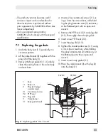
Page 26: ...y gasket seal 3 2 Borehole 4 Threaded bushing 4 1 Radial shaft seal 4 2 Retaining screw 4 3 Washer 4 4 Packing rings 4 5 Spring 5 Actuator base 5 1 O ring 5 2 Washer 5 3 O ring 6 Screw 7 Actuator hous...

Page 27: ...s 12 Pull the actuator plug stem 2 down out of the valve bonnet 3 13 Pull all the packing parts out of the pack ing chamber using a suitable tool Clean the packing chamber thoroughly Renew the packing...

Page 28: ...ing 9 6 Remove the travel indicator 10 7 Use a socket wrench to unscrew the nut 11 from the plug actuator stem while holding the plug actuator stem 2 sta tionary at the flattened part with an open end...

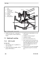
Page 29: ...Body gasket seal 3 2 Borehole 4 Threaded bushing 4 1 Radial shaft seal 4 2 Retaining screw 4 3 Washer 4 4 Packing rings 4 5 Spring 5 Actuator base 5 1 O ring 5 2 Washer 5 3 O ring 6 Screw 7 Actuator...

Page 30: ...s 6 gradually in a crisscross pat tern 28 Replace the body gasket 3 1 See sec tion 7 1 29 Place the valve bonnet 3 with plug 2 onto the body 1 30 Tighten the body nuts 1 1 gradually in a crisscross pa...

Page 31: ...base 5 can still rotate on the slip washers 5 2 21 Screw tight the retaining screw 4 2 at the side to fix the threaded bushing in place 22 Place the spring 9 together with the washer 9 1 onto the actu...

Page 32: ...can be downloaded from our website at u www samson de Services Check lists for after sales service Declaration on Contamination 4 Send the valve together with the filled in form to your nearest SAMSO...

Page 33: ...heck the signal pressure Check the signal pressure line for leakage Plug actuator stem does not move through the whole range Signal pressure too low Check the signal pressure Check the signal pressure...

Page 34: ...in the plant In the event of a valve malfunction 1 Close the shut off valves upstream and downstream of the control valve to stop the process medium from flowing through the valve 2 Check the valve fo...

Page 35: ...tive clothing safety gloves and eyewear Risk of burn injuries due to hot or cold com ponents and pipeline Valve components and the pipeline may be come very hot or cold Risk of burn injuries Allow com...

Page 36: ...iaries representatives and service facilities worldwide can be found on the SAMSON website u www samson de or in all SAMSON product catalogs Required specifications Please submit the following details...

Page 37: ...EB 8140 EN 37...

Page 38: ...38 EB 8140 EN...

Page 39: ...EB 8140 EN 39...

Page 40: ...SAMSON AG MESS UND REGELTECHNIK Weism llerstra e 3 60314 Frankfurt am Main Germany Phone 49 69 4009 0 Fax 49 69 4009 1507 samson samson de www samson de EB 8140 EN 2017 11 29 English...

Reviews: