Mounting and
Operating Instructions
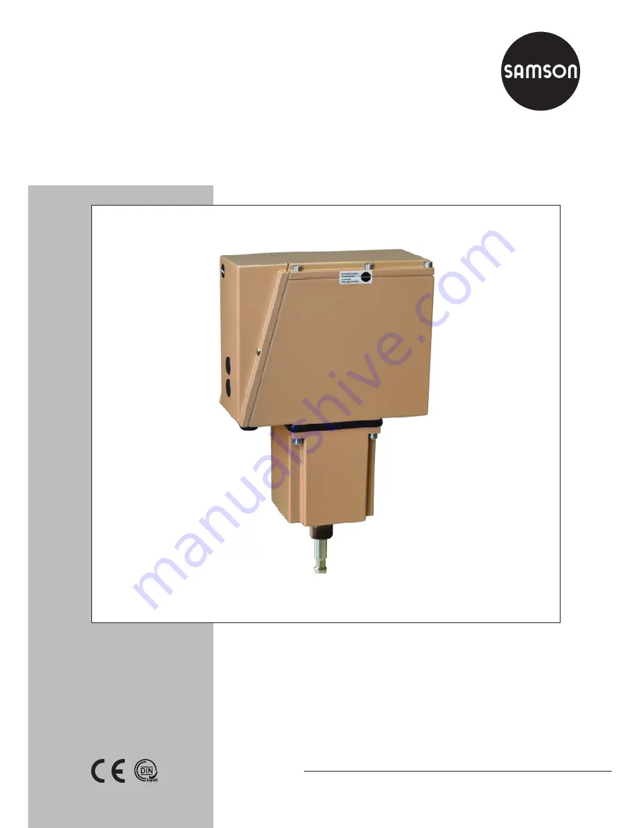
EB 8340 EN
Tr
anslat
ion of original instruct
ions
Edition October 2016
Type 3274 Electrohydraulic Actuator
Page 1: ...Mounting and Operating Instructions EB 8340 EN Translation of original instructions Edition October 2016 Type 3274 Electrohydraulic Actuator...
Page 2: ...partment aftersalesservice samson de The mounting and operating instructions for the devices are included in the scope of delivery The latest documentation is available on our website www samson de Pr...
Page 3: ...6 Manual operation of actuator 18 6 1 Version with electric override 18 6 2 Version with mechanical override 20 7 Operation 21 7 1 Positioners 21 7 1 1 SW1 Priority circuit 22 7 1 2 SW2 Direction of a...
Page 4: ...standards Any hazards that could be caused in the valve by the process medium and the operating pressure or by moving parts are to be prevented by taking appropriate precautions The device is designed...
Page 5: ...VA 110 V 230 V 50 Hz with faster motor 150 VA 110 V 230 V 60 Hz with faster motor 185 VA Positioner 3 VA Permissible ambient temperature 2 10 to 60 C Extended range with heating resistor 40 to 60 C P...
Page 6: ...sponding to isolating switch amplifier used Heating Approx 45 W ON 10 C OFF 0 C through installed thermostats Materials Housing and cover Die cast aluminum Cylinder Hydraulic cylinder tube Piston Stee...
Page 7: ...ail safe position actuator stem re tracts or actuator stem extends in the event of a power supply failure 3 1 Versions The following versions see technical data on page 5 for details are available Wit...
Page 8: ...nserted to activate the override function In combination with a release but ton on the top of the actuator housing the actuator stem can be extended or retracted Versions with fail safe action have a...
Page 9: ...eservoir 2 Cylinder housing 3 Terminal box 5 1 Cylinder 5 2 Piston 5 4 Stem connector 5 6 Actuator stem 5 7 Compression spring 5 8 Compression spring 6 1 Motor 6 2 Gear pump 6 3 Check valve 6 4 Pilot...
Page 10: ...chanical changeover switches which are actuated by continuously adjust able cam disks The motor is switched off by force dependent fixed switches in the actua tor housing 1 Actuators with fail safe ac...
Page 11: ...tion Restriction apply to actuators with mechanical override and or integrated heating see Fig 2 Any mounting position possible Restriction apply to actuators with mechanical override Type 3274 15 16...
Page 12: ...main connected to L and N while mounting the actuator to keep the actua tor stem in the top end position DN 15 to 80 Series 240 1 Replace the stem connector nut 9 3 with an external 10 mm on the valve...
Page 13: ...on 8 Actuator 8 1 Ring nut 5 6 Actuator stem 8 2 Stem connector 9 1 Valve bonnet 9 2 Travel indicator scale 9 3 Stem connector nut 9 4 Lock nut 9 5 Plug stem 8 8 1 5 6 8 2 9 3 9 4 9 2 9 5 9 1 x Fig 3...
Page 14: ...nd a relay in the motor electronics How to proceed Unscrew the side housing cover Guide the cables through the cable glands on the housing to the terminals and connect them see Fig 4 to Fig 6 or circu...
Page 15: ...74 11 18 21 23 3274 13 14 17 18 22 A controller output which issues the eL and aL signals must only be supplied over terminal 81 internal power supply of the actuator Retracts Extends Heating resistor...
Page 16: ...23 3274 13 14 17 18 22 0 4 20 mA 0 4 20 mA 0 2 10V 0 2 10V Retracts Extends Heating resistor Priority circuit White Green Brown Jumper required with 0 2 to 10 V position feedback Input control signal...
Page 17: ...Heating resistor Controller Retracts Extends Position feedback Safety interlock circuit for Type 3274 2x external wiring A controller output which issues the eL and aL signals must only be supplied ov...
Page 18: ...terminal 81 Fig 7 To do this proceed as follows 1 Switch off the power supply 2 Unscrew the two fastening screws and remove the side housing cover 3 Position a screwdriver at the isolating ter minal 8...
Page 19: ...ton 7 Marking pin 8 Isolating terminal 9 Pushbutton extend the actuator stem 10 Pushbutton retract the actuator stem 11 Resistance transmitter 12 Limit contact s 13 Slider switch for version with posi...
Page 20: ...he rack and pinion gear until the require actuator stem position has been reached As soon as the button is released the actua tor reacts again to the controller signal If the valve is to remain in the...
Page 21: ...be added according to Fig 8 In this case valve 1 must be set from 11 5 to 4 mA and valve 2 from 12 5 to 20 mA corresponding values apply to voltage input signals Adjusters and slider switches The adj...
Page 22: ...82 and 83 are connected priority operation is activated and the actuator stem moves to the defined end position After the connection is interrupted the actuator stem follows the control signal The fai...
Page 23: ...llen key 3 Position the segment gear S1 with the corresponding arrow tip depending on the valve rated travel 15 or 30 mm pointing towards the axis of the potentiometer P1 15 30 P1 S1 P2 Segment for 15...
Page 24: ...LED turns off Turn it slightly further until the LED lights up again 9 Use the override to move the valve to the top end position retract the actuator stem 10 Set the voltage or current source to 10 V...
Page 25: ...ights up again 18 Connect isolating terminal 81 Red marking pin Release button 7 1 5 Using the positioner as a position transmitter The positioner can be used as a position transmitter with three step...
Page 26: ...tion the segment gear S1 with the corresponding arrow tip depending on the valve rated travel 15 or 30 mm pointing towards the axis of the potentiometer P1 15 30 P1 S1 P2 Segment for 15 mm travel Segm...
Page 27: ...r stem to the lower end position 2 Position the segment gear S1 with the corresponding arrow tip depending on the valve rated travel 15 mm or 30 mm pointing towards the axis of the potentiometer P1 15...
Page 28: ...he adjustment screw at the contact cam 3 Check the switching point by stroking the actuator Inductive limit contact For the operation of inductive contacts isolating switch amplifiers according to EN...
Page 29: ...EB 8340 EN 29 Dimensions in mm 8 Dimensions in mm 8 1 Actuator with mechanical override 235 110 16 11 5 M30 x 1 5 300 412 H1 185 15 35 125 150...
Page 30: ...30 EB 8340 EN Dimensions in mm 8 2 Actuator with electric override 125 235 110 16 11 5 M30 x 1 5 150 300 320 75 185 15 35...
Page 31: ...EB 8340 EN 31...
Page 32: ...SAMSON AG MESS UND REGELTECHNIK Weism llerstra e 3 60314 Frankfurt am Main Germany Phone 49 69 4009 0 Fax 49 69 4009 1507 samson samson de www samson de EB 8340 EN 2017 06 21 English...