background image

12  

EB 8059 EN

Markings on the device

2  Markings on the device

2.1  Valve nameplate

6

8

12

13

10

11

14 15 16 17

1…5

9

SAMSON

20

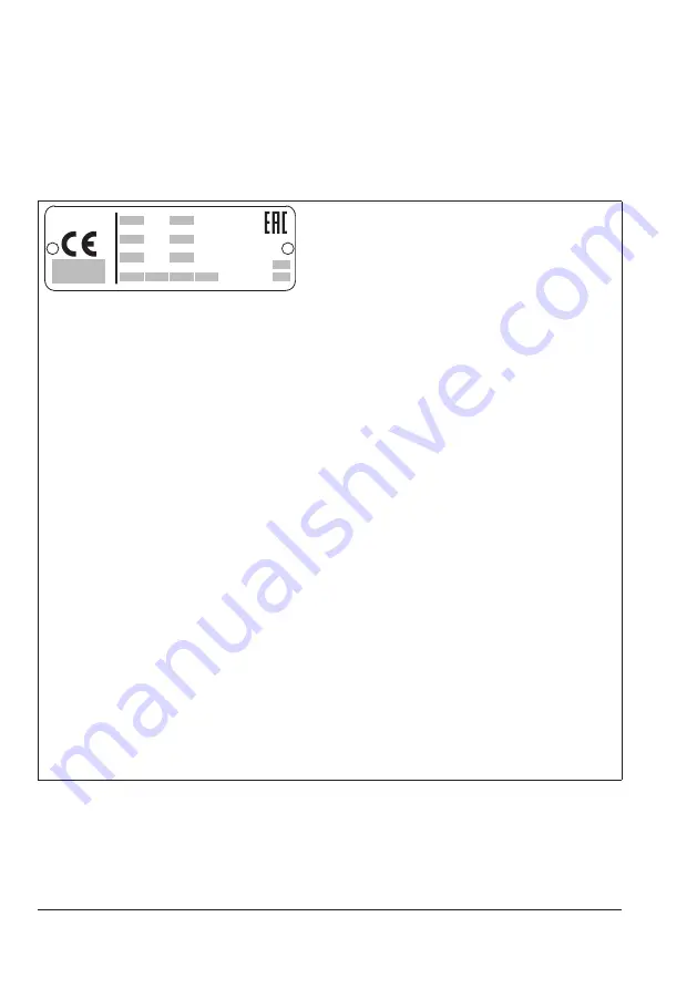
Fig. 1: 

Valve nameplate

1…5

PED (Pressure Equipment Directive), "Art. 4, Abs. 3"
ID of the notified body, fluid group and category

6

Type designation

8

Material

9

Year of manufacture

10

Valve size:

DIN: DN · ANSI: NPS · JIS: DN … A/B

11

Pressure rating:

DIN: PN · ANSI: CL · JIS: K

12

Order no. with modification index

For after-sales service orders: AA prefix

13

Position in order

For after-sales service orders: configuration ID

14

Flow coefficient:

DIN: K

VS

 · ANSI: C

V

 · JIS: C

V

15

Characteristic:

%: equal percentage · Lin: linear · NO/NC: quick opening

16

Seat-plug seal:

ME: metal

HA: carbide metal

ST: Stellite

®

 facing

KE: ceramic

PT: soft seal with PTFE

PK: soft seal with PEEK

17

Seat code (trim material) · On request

20

Country of origin

Summary of Contents for 3259

Page 1: ...Translation of original instructions EB 8059 EN Edition December 2017 Type 3259 Valve In combination with an actuator e g a SAMSON Type 3271 or Type 3277 Pneumatic Actuator...

Page 2: ...fter sales Service Department aftersalesservice samson de The mounting and operating instructions for the devices are included in the scope of delivery The latest documentation is available on our web...

Page 3: ...1 Fail safe positions 14 3 2 Versions 16 3 3 Technical data 16 4 Measures for preparation 20 4 1 Unpacking 20 4 2 Transporting and lifting 20 4 2 1 Transporting 21 4 2 2 Lifting 22 4 3 Storage 25 4 4...

Page 4: ...40 7 4 Replacing the seat and plug 41 7 4 1 Standard version 41 7 4 2 Version with insulating section 43 7 5 Preparation for return shipment 44 7 6 Ordering spare parts and operating supplies 44 8 Ma...

Page 5: ...amage caused by external forces or any other external factors Refer to the technical data and nameplate for limits and fields of application as well as possible uses Reasonably foreseeable misuse The...

Page 6: ...actuators see actuator documentation Warning against residual hazards To avoid personal injury or property damage plant operators and operating personnel must prevent hazards that could be caused in...

Page 7: ...This EU declaration of conformity is included in the Appendix of these instructions see section 10 2 According to the ignition risk assessment performed in accordance with EN 13463 1 2009 section 5 2...

Page 8: ...ush hazard arising from moving parts The control valve contains moving parts actuator and plug stems which can injure hands or fingers if inserted into the valve Do not insert hands or fingers into th...

Page 9: ...le drain the process medium from all the plant sections concerned and the valve Wear protective clothing safety gloves and eyewear Risk of burn injuries due to hot or cold components and pipelines Dep...

Page 10: ...Parts that are too loose may cause leakage Observe the specified tightening torques u AB 0100 Risk of valve damage due to the use of unsuitable tools Certain tools are required to work on the valve On...

Page 11: ...EB 8059 EN 11...

Page 12: ...size DIN DN ANSI NPS JIS DN A B 11 Pressure rating DIN PN ANSI CL JIS K 12 Order no with modification index For after sales service orders AA prefix 13 Position in order For after sales service order...

Page 13: ...tor documentation 2 3 Material number The seat and plug of the valves have an arti cle number written on them Specifying this article number you can contact us to find out which material is used Addit...

Page 14: ...rection of action the actuator stem retracts or extends As a result the plug position in the seat changes and determines the flow rate through the valve 3 1 Fail safe positions The fail safe position...

Page 15: ...9 EN 15 Design and principle of operation S A26 27 17 A7 A8 A4 A10 56 7 5 1 4 14 2 15 60 92 8 10 57 111 S Fig 3 Type 3259 Valve with Type 3271 Pneumatic Actuator left and Type 3277 Pneumatic Actuator...

Page 16: ...orce If the travel range of the actuator is larger than the travel range of the valve the spring assembly in the actuator must be preloaded so that the travel ranges match See associ ated actuator doc...

Page 17: ...0 C High temperature packing 10 to 350 C Body with Insulating section 10 to 450 C Bellows seal 10 to 450 C Leakage class according to IEC 60534 4 Valve plug Metal seal IV High performance metal seal V...

Page 18: ...0 1050 1260 1260 2 x 2800 cm 1260 1260 Weight without actuator 45 48 53 100 1 105 1 295 1 305 1 1 The weight of the valve with a 2800 cm or 2 x 2800 cm actuator increases by 30 kg Table 4 Dimensions a...

Page 19: ...ection Type 3259 with bellows seal The associated actuator documentation applies to actuators e g for SAMSON pneumatic actuators u T 8310 1 for Type 3271 and Type 3277 Actuators up to 750v2 cm actuato...

Page 20: ...he valve The protective caps fitted on the valve s inlet and outlet prevent foreign particles from en tering the valve and damaging it Do not remove the protective caps until im mediately before insta...

Page 21: ...er sales Service department can provide more detailed transport and lift ing instructions on request 4 2 1 Transporting The control valve can be transported using lifting equipment e g crane or forkli...

Page 22: ...ing Make sure the slings can be removed from the valve once it has been installed into the pipeline Prevent the control valve from tilting or tipping Do not leave loads suspended when in terrupting wo...

Page 23: ...y bon net and actuator yoke as well as to the rigging equipment e g hook of the crane or forklift see Fig 4 and Fig 5 2 Carefully lift the control valve Check whether the lifting equipment and acces s...

Page 24: ...tuator area of 700 cm or larger The sling only protects the control valve from tilting while being lifted Before lift ing the control valve tighten the sling For lifting in the upright position procee...

Page 25: ...that the ambient air is free of acids or other corrosive media The permissible storage temperature of standard control valves is 20 to 65 C Contact SAMSON s After sales Service department for the stor...

Page 26: ...d temperature range of the valve match the plant conditions size and pressure rating of the pipeline medium temperature etc Check any mounted pressure gauges to make sure they function When the valve...

Page 27: ...ed ports Depending on the valve size the size of the symmetrically arranged V shaped ports var ies The process medium in the valve flows through the V shaped ports as soon as the plug is lifted out of...

Page 28: ...e control valve and pipeline must be supported or suspended The plant engineering company is responsible in this case Premature wear and leakage due to insuffi cient support or suspension In the follo...

Page 29: ...ass Risk of personal injury due to pressurized components and process medium escaping under pressure Do not loosen the screw of the test connec tion while the valve is in operation Safety guard To red...

Page 30: ...he valve Check the travel reading at the travel in dicator scale Fail safe position Shut off the signal pressure line Check whether the valve moves to the fail safe position Adjustable packing A label...

Page 31: ...serve the maximum permissible pres sure for valve and plant The plant operator is responsible for performing the pressure test SAMSON s After sales Service department can support you to plan and perfo...

Page 32: ...injuries due to hot or cold com ponents and pipelines Depending on the process medium valve components and pipelines may get very hot or cold and cause burn injuries Wear protective clothing and safet...

Page 33: ...EB 8059 EN 33...

Page 34: ...valve residual process medium can escape and depending on its properties may lead to personal injury e g chemical burns Wear protective clothing safety gloves and eyewear Risk of burn injuries due to...

Page 35: ...nuts 14 gradually in a crisscross pattern Remove the bolts 13 3 Unscrew the intermediate piece 2 to gether with the plug 5 from the body 1 4 Remove the body gasket 17 Carefully clean the sealing face...

Page 36: ...g nut 9 Stem connector nut 10 Lock nut 14 Body nut 15 Packing 17 Body gasket lens ring gasket 21 Insulating section 57 Threaded flange 60 Yoke assembly 92 Castellated nut 111 Threaded flange 21 17 7 5...

Page 37: ...ob serving the tightening torque 8 Tighten the body nuts 14 gradually in a crisscross pattern Observe tightening torques 9 Mount actuator See associated actuator documentation 10 Adjust lower or uppe...

Page 38: ...castellated nut 92 and lift the yoke 3 off the intermediate piece 2 3 Undo the body nuts 14 gradually in a crisscross pattern Remove the bolts 13 4 Unscrew the intermediate piece 2 to gether with the...

Page 39: ...ten the body nuts 14 gradually in a crisscross pattern Observe tightening torques 18 Screw in the threaded bushing 8 and tighten it Observe tightening torques 19 Place yoke 3 on the intermediate piece...

Page 40: ...nto the insulating section 21 14 Push the insulating section 21 together with the plug 5 into the body 1 Make sure that the threaded flanges 57 111 are positioned parallel to each oth er and that thei...

Page 41: ...diate piece 2 to gether with the plug 5 from the body 1 5 Replace the body gasket 17 See sec tion 7 2 1 6 Unthread the stem connector nut 9 and lock nut 10 from the plug stem 7 Unscrew the threaded bu...

Page 42: ...g nut 9 Stem connector nut 10 Lock nut 14 Body nut 15 Packing 17 Body gasket lens ring gasket 21 Insulating section 57 Threaded flange 60 Yoke assembly 92 Castellated nut 111 Threaded flange 21 17 7 5...

Page 43: ...ew the castellated nut 92 and lift the yoke 3 off the insulating section 21 3 Undo the body nuts 14 gradually in a crisscross pattern Remove the bolts 13 4 Pull the insulating section 21 together with...

Page 44: ...st lower or upper signal bench range See associated actuator docu mentation 7 5 Preparation for return ship ment Defective valves can be returned to SAMSON for repair Proceed as follows to return devi...

Page 45: ...EB 8059 EN 45 Servicing...

Page 46: ...or plug stem does not move through the whole range Signal pressure too low Check the signal pressure Check the signal pressure line for leakage The valve leaks to the atmosphere fugitive emissions The...

Page 47: ...ice department for malfunctions not listed in the table Note 8 2 Emergency action Upon supply air or control signal failure the valve moves to its fail safe position see sec tion 3 1 The plant operato...

Page 48: ...ipeline may be come very hot or cold Risk of burn injuries Allow components and pipelines to cool down or heat up Wear protective clothing and safety gloves 9 1 Decommissioning To decommission the con...

Page 49: ...N AG and its subsid iaries The addresses of SAMSON AG its subsid iaries representatives and service facilities worldwide can be found on the SAMSON website www samson de or in all SAMSON product catal...

Page 50: ...DIN ANSI single attenuation plate with welding ends all fluids 3381 3 DIN ANSI alle Fluide DIN ANSI all fluids 3381 4 DIN ANSI Einzeldrosselscheibe mehrstufig mit Anschwei ende alle Fluide DIN ANSI s...

Page 51: ...EB 8059 EN 51...

Page 52: ...nsulating section 22 Bellows seal 24 Guide bushing 26 Label bellows seal or insulating section 27 Flange 28 Clamping ring 29 Plug for version with bellows seal 31 Washer 32 Bolt 33 Nut 34 Screw 37 Plu...

Page 53: ...57 13 14 24 6 29 22 39 39 37 2 7 5 4 21 7 7 5 4 57 13 14 57 13 14 17 17 8 12 12 12 12 16 16 19 19 11 15 91 91 14 111 56 1 56 92 10 9 85 83 84 81 80 60 8 12 12 16 19 11 15 26 81 33 99 58 32 33 42 43 1...

Page 54: ...54 EB 8059 EN...

Page 55: ...EB 8059 EN 55...

Page 56: ...2018 11 02 English SAMSON AKTIENGESELLSCHAFT Weism llerstra e 3 60314 Frankfurt am Main Germany Phone 49 69 4009 0 Fax 49 69 4009 1507 samson samson de www samson de EB 8059 EN...

Reviews: