


9-24
EB 8052-E EN
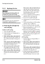
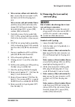
Servicing and conversion
2.
Insert a new spiral gasket (127) into the
body (1) in the seat bridge area.
3. Place seat (4) onto the spiral gasket
(127) in the body (1).
4. Apply a suitable lubricant (114) to the
thread and seating surface of the seat
ring (221). Screw the seat ring (221) by
hand a few turns into the body (1).
5.
Tighten the seat ring (221) using a spe
-
cial tool (
u
AB 0100). Observe tighten-
ing torques.
6.
Valve versions without flow divider:
continue as described in step 7.
Valve version with flow divider:
− Place flow divider (62) and clamping
element (63) into the body (1). Make
sure the parts are properly aligned.
− Insert a new spiral gasket (126) on
top on the clamping element (63).
7. Insert a new spiral gasket (17) into the
body (1).
Valve version without anti-rotation fixture
8.
Standard and LLF 20 packing:
apply a
suitable lubricant (113) to all the packing
parts and to the plug stem (5.1).
HT packing:
do not use any lubricant.
9.
Insert the plug (5) together with the plug
stem (5.1) vertically into the valve body
(1) and position it in the seat (4) in the
closed position.
Version with V-port plug:
align the plug
(5), making sure that the largest
V-shaped port of the V-port plug faces
toward the valve outlet. See information
under 'Mounting the actuator onto the
valve' in the 'Installation' section.
10.
Loosely place the valve bonnet (2) over
the plug stem (5.1) onto the body (1).
11.
Press plug (5) firmly into the seat (4),
while fastening down the valve bonnet
(2) with the body nuts (14). Tighten the
body nuts (14) gradually in a crisscross
pattern. Observe tightening torques.
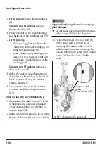
12.
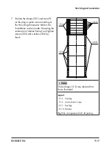
Carefully slide the packing parts over the
plug stem (5.1) into the packing chamber
using a suitable tool. Make sure to ob-
serve the proper order (see Fig. 9-4,
Fig. 9-5 or Fig. 9-6).
13.
LLF 20 packing:
insert packing follower
(8).
Standard and HT packing:
screw in
threaded bushing (8).
14. Place yoke (60) on the valve bonnet (2)
and fasten using the castellated nut (92).
15.
LLF 20 packing:
− Place packing gland (162) over the
studs (164) on the valve body (2) on-
to the packing follower (8).
− Screw the two spring loading assem-
blies (163) onto the studs (164) and
guide them through the holes on the
packing gland.
Standard and HT packing:
continue as
described in step 15.
16. Adjust the packing (see information un-
der 'Adjusting the packing' in the 'Instal-
lation' section > 'Testing the installed
valve' > 'Leak test').
Summary of Contents for 3251-E
Page 6: ...Contents EB 8052 E EN ...
Page 34: ...4 6 EB 8052 E EN ...
Page 86: ...9 28 EB 8052 E EN Servicing and conversion ...
Page 92: ...12 2 EB 8052 E EN ...
Page 94: ...13 2 EB 8052 E EN ...
Page 96: ...14 2 EB 8052 E EN ...
Page 100: ...15 4 EB 8052 E EN ...
Page 101: ......


