


26
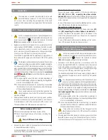
(X32)
(X50)
(X31)
(X36
i
)
(X36
o
)
(X36
o
)
(X36
i
)
(X31)
(X50)
(X32)
(1): (a) (b) (c) (d) (e)
(2) (3)
c b a
d e
1
2 3
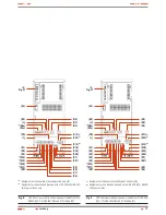
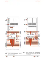
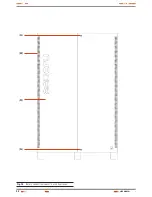
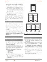
Fig. 21.
Connection of communications for models up to 60 kVA
(LV) / 120 kVA (HV).
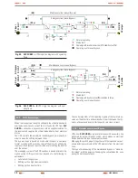
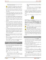
Fig. 22.
Connection of communications for models higher than 60
kVA (LV) / 120 kVA (HV).
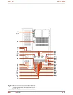
Fig. 23.
Control panel for equipments up to 60 kVA (LV) / 120 kVA
(HV).
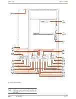
Fig. 24.
Control panel for equipments higher than 60 kVA (LV) /
120 kVA (HV).
4.1.2
Legend corresponding to the equipment views.
Protection and manoeuvring parts (Q*) in the UPS cabinet:
(Q1a)
Input circuit breaker or switch according to the equipment
power rate, two or three poles respectively depending on
the mains typology.
(Q2)
Output switch.
(Q3)
Battery fuse holder switch with 3 fuses in models up to 20
kVA (LV) / 40 kVA (HV) or switch for B1 versions and higher
power rates models.
(Q4a)
Static bypass switch, two or three poles depending on
the mains typology (-B version only).
(Q5)
Manual bypass switch.
Protection and manoeuvring parts(Q*) in the battery cabinet:
(Q8)
Battery fuse holder switch of 3 fuses, for models up to 60
kVA (LV) / 120 kVA (HV).
Battery switch, in models higher than 60 kVA (LV) / 120 kVA
(HV). Also there are 3 fuses
(F8)
with no switch function,
located inside the cabinet.
Connection parts (X*):
(X1)
Terminal of input phase R.
(X2)
Terminal of input phase S.
(X3)
Terminal of input phase T.
(X4)
Terminal of input neutral N.
(X5)
Terminal (copper bar) of main earth
( )
.
(X6)
Terminal of output phase U.
USER MANUAL