background image

11

RIS 400_700PE/PW EKO 3.0

www.salda.lt

[ lt ]

[ it ]

[ en ]

[ de ]

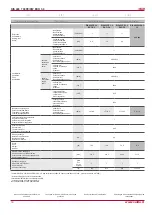
RIS 700PE 1.2 

EKO 3.0

RIS 700PE 3.0 

EKO 3.0

RIS 700PE 4.5 

EKO 3.0

RIS 700PW EKO 

3.0

Šildytuvas

Scambiatore

Heizregister

Heater

- fazė/įtampa

- fase/tensione

- phase/voltage

- Phase/Spannung

[50 Hz/VAC]

~1, 230

~1, 230

~3, 400

AVS 250

- naudojama galia

- potenza assorbita

- power consumption

- Leistungsaufnahme

[kW]

1,2

3,0

4,5

Ventiliatoriai

Ventilatori

Fans

Ventilatoren

- fazė/įtampa

- fase/tensione

- phase/voltage

- Phase/Spannung

[50 Hz/VAC]

~1, 230

šalinimo

estrazione

exhaust

abluft

- galia/srovė

- potenza/corrente

- power/current

- Nennleistung/Nennstrom

[kW/A]

0,168/1.4

- apsisukimai

- velocità di rotazione

- speed

- Drehzahl

[min

-1

]

3230

tiekimo

immissione

supply

zuluft

- galia/srovė

- potenza/corrente

- power/current

- Nennleistung/Nennstrom

[kW/A]

0,168/1,4

- apsisukimai

- velocità di rotazione

- speed

- Drehzahl

[min

-1

]

3230

- valdymo signalas

- segnale di comando

- control input

- Steuerungsignal

[VDC]

0-10

- apsaugos klasė

- classe di protezione

- protection class

- Schutzart

IP-54

Bendra naudojama galia

Potenza assorbita totale

Total power consumption

Total Leistungsaufnahme

- galia/srovė

- potenza/corrente

- power/current

- Nennleistung/Nennstrom

[kW/A]

1,54/8,34

3,34/15,84

4,84/9,34

0,34/2,84

Valdymo automatika sumontuota

Regolazione integrata

Automatic control integrated

Integriertes Steuerungsystem

+

Šiluminis našumas

Resa termica

Thermal efficiency

Thermischer Wirkungsgrad

90%

Sienelių izoliacija

Isolamento dell’involucro

Insulation of walls

Isolation der Wände

[mm]

30

Svoris

Peso

Weight

Gewicht

[kg]

103,5

104

104,5

103

Maitinimo laido skerspjūvis

Sezione del cavo di alimentazione

Cross-section of the power supply cable

Querschnitt Netzkabel

[mm²]

3x1,5

3x2,5

5x1,5

3x1,5

Apsaugos įrenginys*

Dispositivo di protezione*

Circuit breaker*

Sicherungsautomat*

Poliai

Poli

Poles

Polzahl

1

1

3

1

I [A]

B6

B16

B10

Fuse 5A

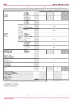
Thermal efficiency of RIS 700PE/PW EKO 3.0 was calculated at 700m³/h (indoor cond20

o

/60%; outdoor conditions -20

o

/90%)

* automatinis jungiklis su B charakteristika

* Interruttore differenziale con caratteristiche B

* automatic switch with characteristic B

*Automatikschalter mit B Charakteristik

Įmonė pasilieka teisę keisti techninius

duomenis

Subject to technical modification

Änderungen in Konstruktion und Design sind 

vorbehalten

La società si riserva di modificare i dati senza 

preavviso

Summary of Contents for RIS 400PE/PW EKO 3.0

Page 1: ...vviso Subject to technical modification RIS 400_700PE PW EKO 3 0_P0023_AP_0004 REKUPERATORINIAI RENGINIAI CENTRALE DI VENTILAZIONE CON RECUPERO DI CALORE AHU WITH HEAT RECOVERY L FTUNGSGER TE MIT W RM...

Page 2: ...eristiche del processore e dei gruppi del sistema 28 Controllo periodico dell unit 31 Garanzia 31 Schema elettrico 34 Tabella di manutenzione del prodotto 62 lt Turinys Transportavimas ir saugojimas 4...

Page 3: ...tion diagrams 34 Product maintenance table 62 de Inhalt Transport und Lagerung 4 Beschreibung 4 Schutzmassnahmen 4 Betriebsbedingungen 5 Bestandeile des Ger tes 6 Bedienung 6 Filter 6 Ventilator 7 W r...

Page 4: ...letzungsgefahr oder Gefahr mechanischer St rungen Bei der Montage und Inbetriebnahme muss Sicherheitskleidung getragen werden Vorsicht die Winkel und Kanten der Anlage und der Kom ponenten k nnen scha...

Page 5: ...supply extract only clean air free of chemical compounds causing metal cor rosion of substances aggressive to zinc plastic and rubber and of particles of solid adhesive and fibred materials The worki...

Page 6: ...ciclo di prova Se durante tale ciclo la temperatura dell aria immessa dovesse scendere sotto il limite im postato dalla fabbrica l unit verrebbe fermata dopo circa 3 minuti Un messaggio che avverte de...

Page 7: ...n acqua e detergente delicato non corrosivo Per pulire la ventola non utilizzare apparecchi ad altapressione prodotti abrasivi strumenti appuntiti e solventi aggressivi che possono graffiare o dannegg...

Page 8: ...a rete elettrica Effettuare i lavori di manutenzione solo quan do tutte le parti dei ventilatori si sono fermate La pulizia dello scambiatore di calore viene effettuata una volta all anno Estrarre del...

Page 9: ...professional If necessary the electrical heater can be re moved Disconnect the electrical connector from the heater and remove the heater Das Elektro Heizregister bedarf keiner zus tz lichen Wartung E...

Page 10: ...do control input Steuerungsignal VDC 0 10 apsaugos klas classe di protezione protection class Schutzart IP54 Bendra naudojama galia Potenza assorbita totale Total power consumption Total Leistungsaufn...

Page 11: ...otal Leistungsaufnahme galia srov potenza corrente power current Nennleistung Nennstrom kW A 1 54 8 34 3 34 15 84 4 84 9 34 0 34 2 84 Valdymo automatika sumontuota Regolazione integrata Automatic cont...

Page 12: ...Gylis Profondit Depth Tiefe L2 mm 46 46 Tiekimo Immissione supply Zuluft F7 F7 Plotis Larghezza Width Breite L mm 300 445 Auk tis Altezza Height H he H mm 220 210 Gylis Profondit Depth Tiefe L2 mm 46...

Page 13: ...the heater works using the same directions the mean temperature difference decreases which affects the heater efficiency If there is a possibility for condensate or water to access the unit external p...

Page 14: ...se utilizzati come opzione devono essere montati il pi lontano possibile dall unit ventilante per quanto permette la lunghezza del cavo del sensore fino alla prima derivazione o curva della rete aerau...

Page 15: ...Es ist notwendig Siphon f r tropfende Kondensat zu verwenden Zubeh r Das Ablaufsystem darf nur in R umen betrieben werden in welchen die Raumtemperatur nicht unter 0 C sinkt Ansonsten muss das System...

Page 16: ...AVS Apvalus kanalinis vandeninis ildytuvas M1 oro ap jimo sklend s By pass pavara PR plok telinis ilumokaitis IV Ventilatore di estrazione PV Ventilatore di immissione RR Scambiatore rotativo R Motor...

Page 17: ...VVP VXP RIS PW EKO 3 0 2 3 eigis vo tuvas Valvola a 2 3 vie 2 3 way valve 2 3 Wege Ventil CO2 CO2 keitiklis Sensore di CO2 CO2 transmitter CO2 sender S 1141 Skirtuminio sl gio keitiklis Sensore di pr...

Page 18: ...3 pozicij valdymo signalas M6 ildytuvo vo tuvo pavara La temperatura dell aria immessa pu essere regolata in base a quella rilevata sull aria estratta impostando il setpoint mediante il pannello di c...

Page 19: ...4 2 e 6 4 3 del manuale FLEX L utente pu regolare la velocit dei ventilatori a tre livelli ciascun livello pu essere modificato the set temperature is not reached the heater electric or water is swit...

Page 20: ...acht der Regler RG1 aus Geschwindigkeit der Ventilatoren f r ZU und Abluft kann synchron oder asynchron geregelt werden siehe Beschreibung des Pults FLEX Punkt II 6 7 und II 6 8 Falls ein Wasserheizer...

Page 21: ...i ripristina autono mamente al rientro nelle temperature di esercizio corrette quella manuale deve essere ripristinata premendo il pulsante rosso RESET sul coper chio della batteria Quando si attiva l...

Page 22: ...ori RS485_1 pannello comando remoto FLEX e RS485_2 rete ModBus oppure pannello comando remoto STOUCH Valore dei contatti del connettore RJ11 1 COM 2 A 3 B 4 24V I microinterruttori 1 e 2 di fig 3 sono...

Page 23: ...ri attivi 01h_Read_Coils 13 1 lt Ventiliatoriai jungti it Ventilatori attivi en Fans ON de L fter EIN 1 Attiva o Inattiva 13 InDumpper 04h_Read_Input 14 1 lt I or s oro sklend s pavara it Servomotore...

Page 24: ...t Speisekabel muss laut elektrischen Param etern der Anlage gew hlt werden falls die Speiseleitung der Anlage fern vom Aggregat ist ist es n tig den Abstand und Spannungs fall zu bewerten Die Anlage m...

Page 25: ...justment works must be done only by qualified and trained personnel Automatic control system of the ventilation unit must be properly adjusted to work adequately Also install measuring and operating d...

Page 26: ...26 RIS 400_700PE PW EKO 3 0 www salda lt lt it en de Set 5 o C...

Page 27: ...des RG1 Reglers 315 mA pr fen Gedimas agregato elektros sujungimuose jungtyse Malfunzionamento del collegamento elettrico morsettiera dell unit Possible unit fault at electrical connections of the un...

Page 28: ...atore i fermo i Fan s not working Ventilator en nicht funktioniert Tiekiamo PV arba i traukiamo IV oro ventiliatoriaus gedimas Malfunzionamento del ventilatore di immissio ne PV o estrazione IV Supply...

Page 29: ...sonda di temperatura con una nuova Verificare il termostato antigelo In condizioni normali la temperatura misurata dalla sonda deve essere maggiore di quella impostata sul termostato il contatto tra...

Page 30: ...30 RIS 400_700PE PW EKO 3 0 www salda lt lt it en de...

Page 31: ...cita I O type Typ I O Maks apkrova Carico massimo Max load Max Be lastung Min apkrova Carico minimo Min load Min Belastung A mA X10 L 230V 50Hz tiekiama tampa L Tensione 230V 50Hz L 230V 50Hz power su...

Page 32: ...50hz Apertura della valvola PWM 24V 50hz Cooling valve opening PWM 24V 50hz ffnen der K hlungsklappe PWM 24V 50hz AO X33 4 VAL Au intuvo sklend s u darymas PWM 24v 50hz Chiusura della valvola PWM 24v...

Page 33: ...M X34 5 A3 Filtr u ter tumo apsauga Protezione intasamento filtri Filter guard Filter Schmutzschutz DI X34 6 A3 COM X34 7 A4 Ventiliatori apsauga Protezione ventilatori Fans guard Fans guard DI X34 8...

Page 34: ...eliver the equip ment to manufacturer Delivery costs should be covered by customer Alle von uns produzierte Ger te sind bei uns ab Werk gepr ft und getestet Sie sind von guten Arbeitsordnung Auf dem G...

Page 35: ...33 18 X33 14 X33 13 X35 1 X35 2 Y1 Control OPEN AC 24 V Y2 Control CLOSE AC 24 V G System potential AC 24 V 24VDC X16 1 2 1 3 X33 5 X33 4 X33 3 VAL VAL VAL Y1 Y2 24VAC 3 position M5 G 11 14 COM B 0 10...

Page 36: ...COM X12 X42 X37 2 X37 1 COM V2 X37 3 X37 4 X4 X3 ModBus RTU RS485_2 RS485_2 A1 A1 A2 A2 A3 A3 TE TE X52 X33 19 X33 20 COM T WAT TJ X33 22 X33 21 X35 3 X35 4 X35 5 N L supply L control N N N EXT EXT EX...

Page 37: ...2 2 1 2 3 X29 1 3x1000W 230V KE1 A2 A1 PWM 0 TK TK RG2 Lin Lout 9 8 7 6 24VDC 24VDC X41 1 X41 2 X39 2 X39 1 X38 1 X38 2 X40 3 X40 2 X40 1 X34 8 X34 7 X34 6 X34 5 X34 4 X34 3 X34 2 X34 1 X33 26 X33 25...

Page 38: ...3 1 Q1 26 24V DC 27 intput 0 10V DC 28 GND Transmitter 2 24 VDC P 28 27 26 X33 22 X33 21 COM T set 16 15 X16 2 HR A4 A4 PUMP AC N L N V1 COM X12 X42 X37 2 X37 1 COM V2 X37 3 X37 4 X4 X3 ModBus RTU RS4...

Page 39: ...COM A 0 10 L X31 24VDC 24VDC X41 1 X41 2 X39 2 X39 1 X38 1 X38 2 X40 3 X40 2 X40 1 X34 8 X34 7 X34 6 X34 5 X34 4 X34 3 X34 2 X34 1 X33 26 X33 25 X33 17 X33 12 X33 18 X33 14 X33 13 X35 1 X35 2 Y1 Cont...

Page 40: ...ze 5x20 Air quality transmitter Supply air pressure Air quality transmitter CO2 Extract air pressure FA Jumper A2 A1 A2 A1 7 2 1 X21 YE GN BU RD PWM STOP NO START NC X33 15 X33 16 COM A 0 10 L X31 24V...

Page 41: ...Jumper FA 7 2 1 X21 YE GN BU RD PWM STOP NO START NC X33 15 X33 16 COM A 0 10 L X31 24VDC 24VDC X41 1 X41 2 X39 2 X39 1 X38 1 X38 2 X40 3 X40 2 X40 1 X34 8 X34 7 X34 6 X34 5 X34 4 X34 3 X34 2 X34 1 X...

Page 42: ...6 7 24VDC 11 14 X16 3 7 8 R1 A1 A2 M4 1f 230V AC PE L N 3 1 P DX Cooling Jumper BOOST STOP NO START NC Transmitter 1 24 VDC 23 24V DC 24 intput 0 10V DC 25 GND Fan fall 1 2W max 1 2W max Fan run P 24V...

Page 43: ...TL 1 2 TE 1 2 U RH TA GN YE RD WH GND RH 5V TA DTJ100 X10 X8 X42 X12 A4 1 A4 2 COM V1 T OUT COM X41 1 X41 2 COM V2 X40 1 X40 2 X40 3 X38 1 X38 2 RG1 V2 5 01 3 2 Components and cables indicated in dott...

Page 44: ...L control M2 3 position 24VAC DC Y1 open Y2 close G M5 M5 Jumper 24VDC 0 10VDC GND Transmitter 2 24VDC 0 10VDC GND Transmitter 1 FA NC NO COM TJ 1 2 24VDC 1 GND 2 open 3 close M1 M1 1 1 X16 2 1 2 2 1...

Page 45: ...01 2017 10 17 2017 10 17 2017 10 17 1 2 3 4 5 6 X22 769 112 7 8 9 10 11 12 PE K1 01 3 3 1 2 3 4 5 6 AT1 1 716 F 2106 aut 50C 2 K1 A1 A2 1 2 01 2 3 3 4 01 2 3 5 6 01 2 3 13 14 01 3 2 K1 RG2 A1 A2 PWM 0...

Page 46: ...21 1 1 2 3 4 5 6 X32 7 8 794821 1 0 10V GND L N PE 0 10V GND L N PE TE 1 2 TL 1 2 W7 white W7 brown W8 white W8 brown X52 X52 X37 X37 X41 Jungtis 1375820 2 MTA CST 100 II MT 1 2 X33 T OUT X33 COM TJ 1...

Page 47: ...ksandravi ius Vent 224 1091 224 1091 0 1 0 PS Pricipal connection scheme 5 01 2017 10 16 2017 10 16 2017 10 16 1 2 3 4 5 6 X32 7 8 794821 1 1 2 3 4 5 6 X33 7 8 794821 1 PE N L 10V TACHO GND 0 10V PV R...

Page 48: ...ME DATE SALDA UAB Drawing Book CHECKED BY 1 1 2 3 4 4 5 6 7 7 EI A klenikas EI K Vasiliauskas Sklend 227 1111 227 1111 0 1 0 PS Pricipal connection scheme 4 01 2017 10 16 2017 10 16 2017 10 16 W12 bla...

Page 49: ...2 TE 1 2 U RH TA GN YE RD WH GND RH 5V TA DTJ100 X10 X8 X42 X12 A4 1 A4 2 COM V1 T OUT COM X41 1 X41 2 COM V2 X40 1 X40 2 X40 3 X38 1 X38 2 RG1 V2 5 01 3 2 Components and cables indicated in dotted l...

Page 50: ...L control M2 3 position 24VAC DC Y1 open Y2 close G M5 M5 Jumper 24VDC 0 10VDC GND Transmitter 2 24VDC 0 10VDC GND Transmitter 1 FA NC NO COM TJ 1 2 24VDC 1 GND 2 open 3 close M1 M1 1 1 X16 2 1 2 2 1...

Page 51: ...18 2017 10 18 2017 10 18 1 2 3 4 5 6 X22 769 112 7 8 9 10 11 12 PE K1 01 3 3 1 2 3 4 5 6 AT1 1 716 F 2106 aut 50C 2 K1 A1 A2 1 2 01 2 3 3 4 01 2 3 5 6 01 2 3 13 14 01 3 2 K1 RG2 A1 A2 PWM 0 TK TK A1 E...

Page 52: ...21 1 1 2 3 4 5 6 X32 7 8 794821 1 0 10V GND L N PE 0 10V GND L N PE TE 1 2 TL 1 2 W7 white W7 brown W8 white W8 brown X52 X52 X37 X37 X41 Jungtis 1375820 2 MTA CST 100 II MT 1 2 X33 T OUT X33 COM TJ 1...

Page 53: ...ksandravi ius Vent 224 1091 224 1091 0 1 0 PS Pricipal connection scheme 5 01 2017 10 16 2017 10 16 2017 10 16 1 2 3 4 5 6 X32 7 8 794821 1 1 2 3 4 5 6 X33 7 8 794821 1 PE N L 10V TACHO GND 0 10V PV R...

Page 54: ...ME DATE SALDA UAB Drawing Book CHECKED BY 1 1 2 3 4 4 5 6 7 7 EI A klenikas EI K Vasiliauskas Sklend 227 1111 227 1111 0 1 0 PS Pricipal connection scheme 4 01 2017 10 16 2017 10 16 2017 10 16 W12 bla...

Page 55: ...COM X41 1 X41 2 COM V2 X40 1 X40 2 X40 3 X38 1 X38 2 RG1 V2 5 01 3 2 Components and cables indicated in dotted line should be connected by the manufacturer or by the user X37 X37 X52 X52 Cable is con...

Page 56: ...L control M2 3 position 24VAC DC Y1 open Y2 close G M5 M5 Jumper 24VDC 0 10VDC GND Transmitter 2 24VDC 0 10VDC GND Transmitter 1 FA NC NO COM TJ 1 2 24VDC 1 GND 2 open 3 close M1 M1 1 1 X16 2 1 2 2 1...

Page 57: ...2017 10 18 1 2 3 4 5 6 X22 769 112 7 8 9 10 11 12 PE K1 01 3 3 1 2 3 4 5 6 AT1 1 716 F 2106 aut 50C 2 K1 A1 A2 1 2 01 2 3 3 4 01 2 3 5 6 01 2 3 13 14 01 3 2 K1 RG2 A1 A2 PWM 0 TK TK K1 01 3 3 13 14 RT...

Page 58: ...21 1 1 2 3 4 5 6 X32 7 8 794821 1 0 10V GND L N PE 0 10V GND L N PE TE 1 2 TL 1 2 W7 white W7 brown W8 white W8 brown X52 X52 X37 X37 X41 Jungtis 1375820 2 MTA CST 100 II MT 1 2 X33 T OUT X33 COM TJ 1...

Page 59: ...ksandravi ius Vent 224 1091 224 1091 0 1 0 PS Pricipal connection scheme 5 01 2017 10 16 2017 10 16 2017 10 16 1 2 3 4 5 6 X32 7 8 794821 1 1 2 3 4 5 6 X33 7 8 794821 1 PE N L 10V TACHO GND 0 10V PV R...

Page 60: ...ME DATE SALDA UAB Drawing Book CHECKED BY 1 1 2 3 4 4 5 6 7 7 EI A klenikas EI K Vasiliauskas Sklend 227 1111 227 1111 0 1 0 PS Pricipal connection scheme 4 01 2017 10 16 2017 10 16 2017 10 16 W12 bla...

Page 61: ...OM X41 1 X41 2 COM V2 X40 1 X40 2 X40 3 X38 1 X38 2 RG1 V2 5 01 3 2 Components and cables indicated in dotted line should be connected by the manufacturer or by the user X37 X37 X52 X52 Cable is conne...

Page 62: ...ply L control M2 3 position 24VAC DC Y1 open Y2 close G M5 M5 Jumper 24VDC 0 10VDC GND Transmitter 2 24VDC 0 10VDC GND Transmitter 1 FA NC NO COM TJ 1 2 24VDC 1 GND 2 open 3 close M1 M1 1 1 X16 2 1 2...

Page 63: ...19 2017 10 19 2017 10 19 AC N PUMP V2 5 02 1 3 02 1 3 COM B 0 10 COM T WAT V2 5 05 1 3 1 29 X16 2 1 30 2 1 31 2 1 32 X16 2 1 33 2 1 34 2 1 35 2 1 36 2 01 3 02 6 Black 0 5 Black 0 5 White 0 5 Black 0 5...

Page 64: ...8 794821 1 0 10V GND L N PE 0 10V GND L N PE TE 1 2 TL 1 2 W7 white W7 brown W8 white W8 brown X52 X52 X37 X37 X41 Jungtis 1375820 2 MTA CST 100 II MT 1 2 X33 T OUT X33 COM TJ 1 2 W9 white W9 brown X...

Page 65: ...ksandravi ius Vent 224 1091 224 1091 0 1 0 PS Pricipal connection scheme 5 01 2017 10 16 2017 10 16 2017 10 16 1 2 3 4 5 6 X32 7 8 794821 1 1 2 3 4 5 6 X33 7 8 794821 1 PE N L 10V TACHO GND 0 10V PV R...

Page 66: ...ME DATE SALDA UAB Drawing Book CHECKED BY 1 1 2 3 4 4 5 6 7 7 EI A klenikas EI K Vasiliauskas Sklend 227 1111 227 1111 0 1 0 PS Pricipal connection scheme 4 01 2017 10 16 2017 10 16 2017 10 16 W12 bla...

Page 67: ...67 RIS 400_700PE PW EKO 3 0 www salda lt lt it en de...

Page 68: ...keitimas Sostituzione dei filtri Filter replacement Filterwechsel Kas 3 4 m nesius Ogni 3 4 mesi Every 3 4 months Alle 3 4 Monate PASTABA Produkt sigij s asmuo privalo pildyti Gaminio prie i ros lente...

Reviews: