5-009
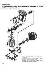
RAMMING SYSTEM
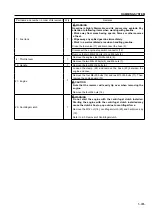
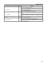
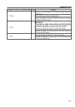
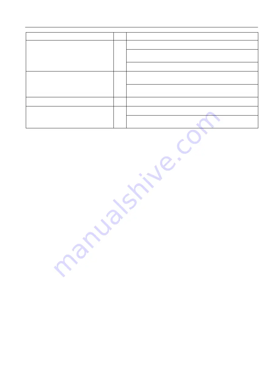
Part name and number in order of its removal
Q’ty
Remarks
4 : Crank case
1
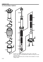
Remove the two M10x40 bolts (16).
Remove the pin (9) and then, remove the crank case assembly (4)
from the cylinder assembly (11).
Remove the ten M6x16 bolts (1) and cover (2).
7 : Connecting rod
1
Remove the C-retaining ring (8) that holds the connecting rod in
place.
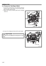
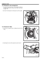
Remove the connecting rod (7). Refer to 3-3. Removal of Connecting
Rod.
6 : Gear
1
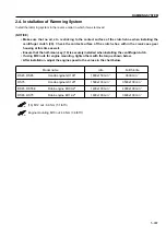
Refer to 3-4. Removal of Gear
.
11: Cylinder assembly
1
Remove the drain plug (12) to drain the cylinder oil.
Remove the four M12 nuts (13) and M12×35 bolts (14). Then remove
the shoe assembly (15).
Summary of Contents for RS45
Page 1: ...RS45 RS55E RS65 RS75 SHOP MANUAL 3498 64694 0 ...
Page 2: ......
Page 4: ......
Page 9: ...SAFETY ...
Page 10: ......
Page 17: ...SPECIFICATIONS ...
Page 18: ......
Page 29: ...INSPECTION AND MAINTENANCE ...
Page 30: ......
Page 37: ...PARTS CATALOGUE ...
Page 38: ......
Page 50: ...4 012 PARTS CATALOGUE 2 4 SHOE ASSY 5 6 7 13 12 11 10 9 8 1 2 3 4 16 15 14 17 ...
Page 70: ...4 032 PARTS CATALOGUE 3 4 SHOE ASSY 5 6 13 16 15 14 12 11 10 1 2 3 4 9 8 7 17 ...
Page 76: ...4 038 PARTS CATALOGUE 3 7 NAME PLATE VIEW A A VIEW B B 12 11 2 15 5 9 4 1 3 7 8 10 13 14 ...
Page 92: ...4 054 PARTS CATALOGUE 4 4 SHOE ASSY 8 3 5 4 4 6 5 7 2 1 ...
Page 122: ...4 084 PARTS CATALOGUE 5 4 SHOE ASSY 8 3 5 4 4 6 5 7 2 1 ...
Page 136: ......
Page 137: ...RAMMING SYSTEM ...
Page 138: ......
Page 155: ......


