background image

13

Detail

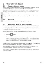
3.9

Channel scanning

Scanning is an extension to the dual watch functionality, by which it is possible to watch
multiple channels. It is possible to scan:

All channels in a sequence

A number of selected channels in a sequence organized into individual 3 scan tables
- Scan table A, B and C.

The scan type can be selected from the Scanning menu (3). The DW indicator is lit as well
(because the priority channel 16 by default is included in any scan table).

During the scan “SC” is shown in the upper display.

If an active signal is found on a channel different from channel 16 the radio remains on that
channel for 4 seconds (but still respecting dual watch requirements), where after scanning is
resumed. The telephone display is displaying the active channel.

If an active signal is found on channel 16, the VHF is locked on channel 16 until the signal
disappears, where after scanning is resumed. The telephone display is displaying the active
channel (16).

While the active scanning window is visible, scanning can be terminated by:

Lifting the handset off the hook

Pressing ´16´ - Channel 16 is used as working channel

Pressing DISTRESS – Initiates DSC distress

Pressing 

 – Working channel is used as before scanning was entered

(regardless of carrier state).

Pressing Replay - Message is replayed

Pressing any numeric key - Normal channel entry

If scanning is terminated while no active signal was found, the VHF will receive on the
working channel (as it was before scanning was initiated).

If scanning is terminated (handset hook-off) while an active signal is received, the VHF will
operate on this channel after termination.

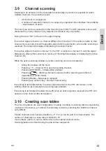
3.10

Creating scan tables

The scanning tables are user configurable. Creating or editing a scanning table by organizing
a subset of channels (e.g. Table A) for scanning is done by selecting the Edit Scan Table A
entry (3.5.1).

Private channels (non-numeric identifiers – P, F or L) can be part of a channel table. The
number of channels in a scan table is limited to 16.
3 scan tables (A,B & C) can be defined for each enabled channel mode.
Scanning tables are stored during the power-down sequence.

0544

Summary of Contents for RT5022 VHF DSC

Page 1: ...SAILOR RT5022 VHF DSC SAILOR RT5020 VHF DSC Duplex OPERATION MANUAL...

Page 2: ......

Page 3: ...ons used in this manual ADDR Address BI Channel mode when sailing on European rivers BQ DSC Call Acknowledgement Reply CU Control Unit DSC Digital Selective Calling DW Dual Watch EOS DSC End Of Sequen...

Page 4: ...hat energy beyond FCC allowable limits for occupational use and thus to avoid health hazards from excessive exposure to RF energy FCC OET bulletin 65 establishes an Maximum Permissible Exposure MPE ra...

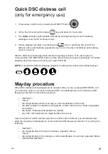
Page 5: ...tained by pressing the following keys Mayday procedure When DSC distress acknowledgement is received after you have pressed DISTRESS or if you otherwise need to commence distress traffic via radiotele...

Page 6: ...hannel system activated Is used when sailing on any sea in the world except in US waters US US channel system activated Is used when sailing in US Waters BI BI channel system activated Is used when sa...

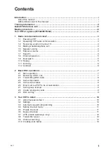
Page 7: ...ion 5 1 9 Dual watch 5 1 10 Replay 5 1 11 Dimming 6 1 12 Contrast 6 2 Basic DSC operations 7 2 1 Menu operation 7 2 2 Receiving a DSC call 7 2 3 Transmitting DSC Calls 8 2 4 Call a ship station 8 2 5...

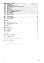
Page 8: ...ing 25 5 2 Troubleshooting 25 6 Menu tree 29 7 Optional functional devices 31 7 1 Semi functional control unit 31 7 2 Alarm panel 35 7 3 Printer 36 8 Maritime Channels 37 8 1 International channels 37...

Page 9: ...hted TX indicator Receive mode is always reached by releasing the PTT button P T T P T T Press PTT Release PTT hooked off hooked on Handset Handset Transmit and receive is performed on the working cha...

Page 10: ...e the PTT key to listen 5 When answered agree upon a channel switch to that channel for example channel 6 and begin your conversation Press PTT only when you are talking If on a simplex channel in oth...

Page 11: ...ll continue dual watch on the new selected working channel unless a signal is found on channel 16 1 10 Replay Replay is a facility built into the product which always will allow the operator to repeat...

Page 12: ...adjust the light intensity the dim button is pressed While the dim button is pressed the intensity is changing Releasing the dim button will maintain the current light intensity A renewed pressing of...

Page 13: ...u window normally one level up If is pressed in the main menu the menu will be turned off Selecting the menus for transmitting DSC calls will lead to a sequence of windows flows The flow sequences are...

Page 14: ...y if it is not available via the contact list Please also refer to Section 4 1 2 for using extended sub addressing 2 5 Call a shore station To call a shore station enter the Station Call menu 1 1 and...

Page 15: ...each 3 4 minutes The distress mode can be exited only by reception of the appropriate distress acknowledgement call or if you press for 5 seconds or if you power off the VHF The VHF will start up in...

Page 16: ...nel is selected squelch level is inherited from either the global setting or a stored squelch level for that particular channel default is that all channels are using the global squelch level Storing...

Page 17: ...nel Using the will simply make the private channel number appear above the highest numeric channel number 30 3x10 private channels are available for each enabled channel mode Note In US mode private c...

Page 18: ...Phonetic Value Character Phonetic Value A Alpha 1 N November 14 B Bravo 2 O Oskar 15 C Charlie 3 P Papa 16 D Delta 4 Q Quebec 17 E Echo 5 R Romeo 18 F Foxtrot 6 S Sierra 19 G Golf 7 T Tango 20 H Hotel...

Page 19: ...el 16 While the active scanning window is visible scanning can be terminated by Lifting the handset off the hook Pressing 16 Channel 16 is used as working channel Pressing DISTRESS Initiates DSC distr...

Page 20: ...hing all 10 digits in the MMSI number Transmitted routine calls or acknowl edgements to individual routine calls are using the self ID with non zero digit 10 If X10 is programmed to zero the unit reac...

Page 21: ...ways according to the nature of the call as shown in the following diagram 60 sec 1 sec 8 sec 3 sec 5 sec 3 1 2 4 1 2 min 3 sec 3 1 2 4 1 2 min 3 sec 3 1 2 4 1 2 min 3 sec DISTRESS URGENCY TONE SIGNA...

Page 22: ...ntact 1 Call Contact 4 5 1 Calling a contact It is possible to initiate the following calls from the Call Contact menu item 2 1 Individual station ships or coast routine radiotelephony calls Group rou...

Page 23: ...n the call flow with the selected number information pre filled 4 5 2 Show contact Via the menu item 2 2 it is possible to search for a contact s information without changing or initiate anything 4 5...

Page 24: ...using these calls it will work in the following way After powering up normally the VHF it will not be possible to use these call types message Call type not enabled in VHF if selected Each of the cal...

Page 25: ...urgency will alert continuously until manually handled from the front panel 4 7 Implicit behaviour for operations with DSC This section describes assumptions and decisions made that are critical for...

Page 26: ...be changed to Unable to Comply 104 on operator s request stating the selected reason For all received or transmitted calls the full information can be retrieved from the DSC log 4 7 4 Receiving DSC ca...

Page 27: ...adio goes into activity mode the idle mode will just leave the screen blank To display the position and identity information quickly in this mode briefly activate press the on off button This will res...

Page 28: ...available The voice scram bling option is enabled by entering of a pin code key into the VHF transceiver This pin code is uniquely matched to the serial number of the VHF i e one specific pin code wi...

Page 29: ...creen The scrambling mode is abandoned in the following situations Hook on see also 7 1 15 Press Press Press Receiving Distress or an Urgency call types Please note that some country authorities may r...

Page 30: ...ill start as X YY 00 small changes will add up ie e X YY 01 X YY 02 etc For software releases with only the zz index increased Notified Body will be informed only without the need for updating the cer...

Page 31: ...s pop up and information windows shall be logged in the event logging system for later read out The error logs are accessed from menu 4 6 3 1 From menu 4 6 3 2 at least the following statistics are av...

Page 32: ...y test All push buttons can be checked using the self test in menu 5 1 Pressing or releasing any key on the front panel will be echoed in the graphic display Only exception is DISTRESS and ON OFF whic...

Page 33: ...to this Sparc II connector or via the Connection Box and or Extension Box refer to installation section in the back of this manual In case of an Alarm Panel AP4365 being connected to the VHF check an...

Page 34: ...on of a DSC call which is not of category distress or urgency will be postponed if the VHF is already in the process of decoding an incoming DSC call As soon as this decoding process has finalized the...

Page 35: ...d Distress 1 5 4 2 Print Receive Log 1 5 4 3 Print Transmit Log 1 5 4 4 All Incoming DSC As Text As Symbols Disable 1 5 4 5 All Outgoing DSC As Text As Symbols Disable 2 Contacts 2 1 Call Contact 2 2...

Page 36: ...lue of X10 digit 4 5 6 2 X10 0 mode Acknowledge Non zero Acknowledge Zero Reject Call 4 6 System 4 6 1 Device Identification 4 6 1 1 SW Version 4 6 1 2 Serial Number 4 6 2 Idle Display Blank Display 4...

Page 37: ...ce printer server 7 1 Semi functional control unit The semi functional control unit CU5000 is an optional unit connecting an additional remote handset to the VHF Installation of control units should b...

Page 38: ...requests are sent to the main VHF unit and the main VHF unit will change channel and update the CU display The same channel number will be applied to all the displays in the system A quick channel 16...

Page 39: ...h programming 7 1 7 Dimming Dimming the control unit display and keypad backlight and 1W LED is done exactly as described for the VHF but with no graphical information 7 1 8 Receiving a DSC call If a...

Page 40: ...eived voice is heard in the speakers 7 1 10 Transmitter power Pressing the 1W button will have the same effect as described for VHF 1W LED on CU will follow the 1W LED on the main unit 7 1 11 Replay T...

Page 41: ...minated with a hook on of the handset The following approach is taken for installations with CU5000 The terminating action is only taking place if the handset that was hooked on was the last active ha...

Page 42: ...up to the VHF equipment should be performed by authorised and properly trained service personnel only Individual messages from the DSC call logs may be printed The entire content of each DSC log may...

Page 43: ...6 650 72 156 625 156 625 14 156 700 156 700 73 156 675 156 675 15 156 750 156 750 74 156 725 156 725 16 156 800 156 800 Distress and calling 75 156 775 156 775 L 17 156 850 156 850 76 156 825 156 825...

Page 44: ...800 Distress and calling 75 B 17 156 850 156 850 76 B 18 156 900 156 900 77 156 875 156 875 L 19 156 950 156 950 78 156 925 156 925 20 157 000 157 000 79 156 975 156 975 21 157 050 157 050 80 157 025...

Page 45: ...L L 74 156 725 156 725 L 16 156 800 156 800 Distress and calling 75 156 775 156 775 L 17 156 850 156 850 L L 76 156 825 156 825 L 18 156 900 161 500 77 156 875 156 875 L 19 156 950 161 550 78 156 925...

Page 46: ...ling 75 B 17 156 850 156 850 L 76 B 18 156 900 156 900 77 156 875 156 875 L 19 B 78 156 925 156 925 20 157 000 161 600 L 79 156 975 156 975 21 161 650 RX 80 157 025 157 025 22 B 81 B 23 157 150 161 75...

Page 47: ...41 Installation 9 Installation 9 1 Mounting possibilities VHF with mounting bracket 39835 256 140 200 100 229 Relief bracket for handset cable 99 126905 0833...

Page 48: ...9 kg Mounting bracket 1 0 kg VHF with flush mounting bracket 39938 Bracket Option Space for Cable entry min 100 00 240 120 3 Drilling plan 39945 228 10 219 9 102 6 108 6 20 20 20 20 4 pcs 5 4 pcs 3 5...

Page 49: ...hich is activated by a small magnet embedded in the ceadle The cradle must be installed as illustrated in order to ensure the hook on off functionality of the Handset 75 62 226 120 min 200 Space for h...

Page 50: ...Installation with 2 CUs If an installation is carried out providing 2 new CUs it is important when powering these up for the first time that this is done sequentially to allow the CUs to acquire thei...

Page 51: ...Installation Connection box 4 pcs 6 Drilling plan 39656 Free space for cable entry Free space for mounting Mounting 185 14 85 239 9 75 258 4 225 4 49 50 min 100 50 50 Weight Connection box 1 7 kg 060...

Page 52: ...46 Installation Extension box 4 pcs 6 Drilling plan 39657 Free space for cable entry Free space for mounting Mounting 141 4 160 4 49 50 min 100 50 50 122 9 7 14 85 120 Weight Extension box 0 7 kg 0605...

Page 53: ...tance Safe distance in accordance with Annex A of ISO 694 2000 Device After magnetization RT5022 Transceiver Unit 80 cm C5001 Handset 85 cm C5000 Semi functional Control Unit 85 cm CB5009 Connection B...

Page 54: ...nstallation 9 3 Interface connections VHF rear view 39815B FUSE Option Sparc II Bus Handset 12 24V DC Main Antenna DSC Antenna 15 pin sub D male 15 pin sub D female 9 pin sub D female Power connector...

Page 55: ...AND J3 J4 FOR X5 ALARM NMEA SPARC II BUS 1 6 5 7 4 3 2 9 8 10 15 14 11 12 13 1 6 2 3 4 7 5 14 10 8 9 13 12 15 X5 X9 EB CU X8 15 11 11 OPTIONS 12 13 9 RT50XX OPTIONS 8 X6 10 14 5 7 4 3 2 6 1 X2 15 13...

Page 56: ...h LAN Box VHF L 3m Optional Optional Ext speaker CU Ext speaker VHF CU 2 Optional L 3m Handset PL259 RX TX Antenna RG214 or better PL259 Power 12 24V DC Cable L 1 5m furnished with equiptment Optional...

Page 57: ...S X1 12 5V 8 12 13 15 GND 14 EXT LS 11 7 3 10 6 Line out 1 5 2 4 X5 X6 X4 9 8 Line out 9 EXT LS CU LS 12 5V GND EB CU CB RT50XX CU 12 5V DATA CU LS X6 X3 X2 10 12 13 15 14 EB CU EXT CU LS EB CU RT50XX...

Page 58: ...e programming see note 1 Sparc II Connections VHF Signal Cable Connection box Connection box Connection box Connection box Alarm panel Signal description Ships cable SPARC connector designation p n 56...

Page 59: ...e securely grounded at cable inlets in connection boxes 120W min continuous Power cable p n 539826 1 5m 2x4 0mm2 VDC White or red 0 VDC Black rear view 56 114 L 5m VHF DSC Antenna RG214 or better PL25...

Page 60: ...ower to CUs pair no 6 pin 8 RX_AF Green Wht X2 8 X1 8 Grn Wht X3 8 pair no 3 pin 9 RX_AF Green X2 9 X1 9 Grn X3 9 pair no 3 pin 10 12 5VDC Blk Wht X2 10 X1 10 Blk Wht X3 10 Power to CUs pair no 7 pin...

Page 61: ...stallation reference is made to the IMO COMSAR Circ 32 GUIDELINES FOR THE HARMONIZATION OF GMDSS REQUIRE MENTS FOR RADIO INSTALLATIONS ON BOARD SOLAS SHIPS 9 5 2 RX TX antenna In installations consist...

Page 62: ...he DSC receiver of a VHF is likely to be temporarily blocked in reception due to high signal blocking if the associated DSC antenna is installed in close vicinity of a RX TX antenna at the same horizo...

Page 63: ...on Scanning Priority scanning All channels or scanning up to 3 user programmable scan tables in each channel mode Voice replay Voice replay facility of up to 90 seconds of received voice data Automati...

Page 64: ...Adjacent channel selectivity more than 74 dB Blocking level more than 94 dB V Transmitter RF output power High 25W 0dB to 0 5dB Low 0 85 W 0 5dB to 1dB Adjacent channel power below 75 dB Conducted sp...

Page 65: ...low 5 S N ratio more than 43 dB Spurious emission below 0 25 nW Spurious response rejection more than 74 dB Intermodulation response more than 73 dB Co channel rejection better than 10 dB Adjacent cha...

Page 66: ......

Page 67: ......

Page 68: ...Thrane Thrane A S info thrane com www thrane com B5022GB0 Issue L 09 02...

Reviews: