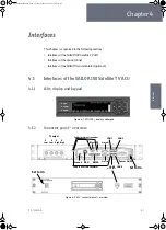
Interfaces of the SAILOR 100 Satellite TV ACU
98-136280-B
Chapter 4: Interfaces
4-3
4444
In
te
rf
ac
es
4.1.4
ADU connector
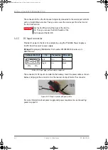
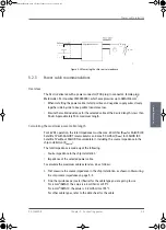
There is just one cable from the ACU to the ADU. This is used to power the ADU, handle
all communication between ACU and ADU, and deliver the Rx signal.
4.1.5
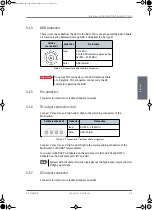
Rx connector
Connector for internal use (cable already connected).
4.1.6
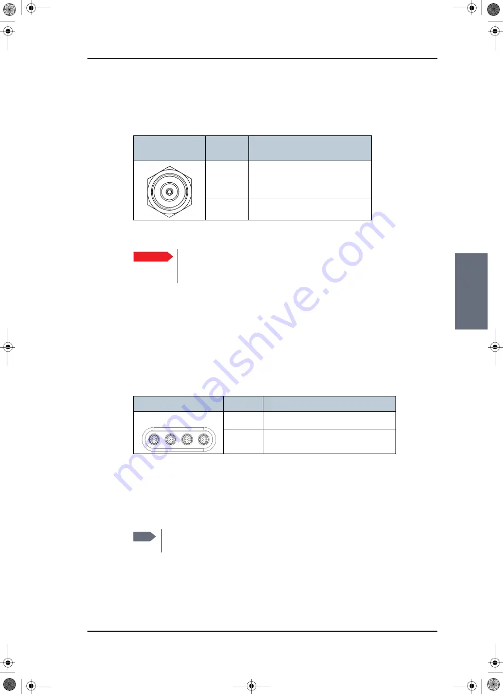
TV output connectors (x4)
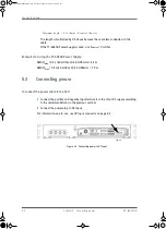
Connect V Low, H Low, V High and H High to the matching connectors of the
Multiswitch.
Connect V Low, H Low, V High, and H High to the corresponding connectors of the
Multiswitch or SAILOR Transmodulator.
In circular mode RHCP is delivered on the vertical ports (VL and VH) and LHCP is
delivered on the horizontal ports (HL and HH).
4.1.7
DC output connector
Connector for internal use (cable already connected).
Outline
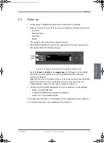
(on the ACU)
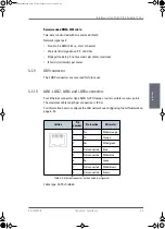
Conductor
Pin function
Inner
DC to ADU
ACU to ADU internal communication
Rx (950 — 5450 MHz)
Outer
GND (Shield)
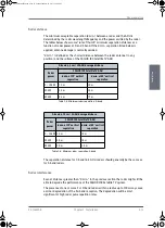
Table 4-2: N connector, outline and pin assignment
Important
Do not use TNC connectors on the ADU antenna cable
or on pigtails. TNC connectors cannot carry the DC
current for operating the ADU.
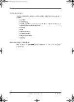
Outline (on the ACU)
Conductor
Pin function
Inner
Rx (950 — 2150 MHz)
Outer
GND (Shield)
Table 4-3: F connector, Rx, outline and pin assignment
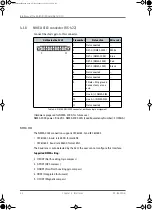
Note
Systems with circular polarisation typically use the high band only (connectors
V High and H High).
SAILOR100IM.book Page 3 Friday, January 18, 2013 10:28 AM
Summary of Contents for 100
Page 1: ...INSTALLATION MANUAL SAILOR 100 Satellite TV ...
Page 2: ......
Page 8: ...vi 98 136280 B SAILOR100IM book Page vi Friday January 18 2013 10 28 AM ...
Page 141: ...Appendices SAILOR100IM book Page 1 Friday January 18 2013 10 28 AM ...
Page 142: ...SAILOR100IM book Page 2 Friday January 18 2013 10 28 AM ...
Page 178: ...Glossary Glossary 4 98 136280 B SAILOR100IM book Page 4 Friday January 18 2013 10 28 AM ...
Page 185: ......

