Installation of the ACU
98-136280-B
Chapter 3: Installation
3-23
3333
In
stall
ati
o
n
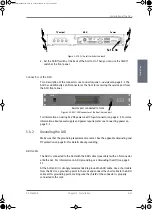
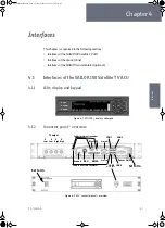
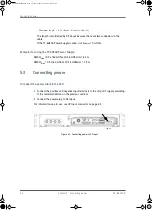
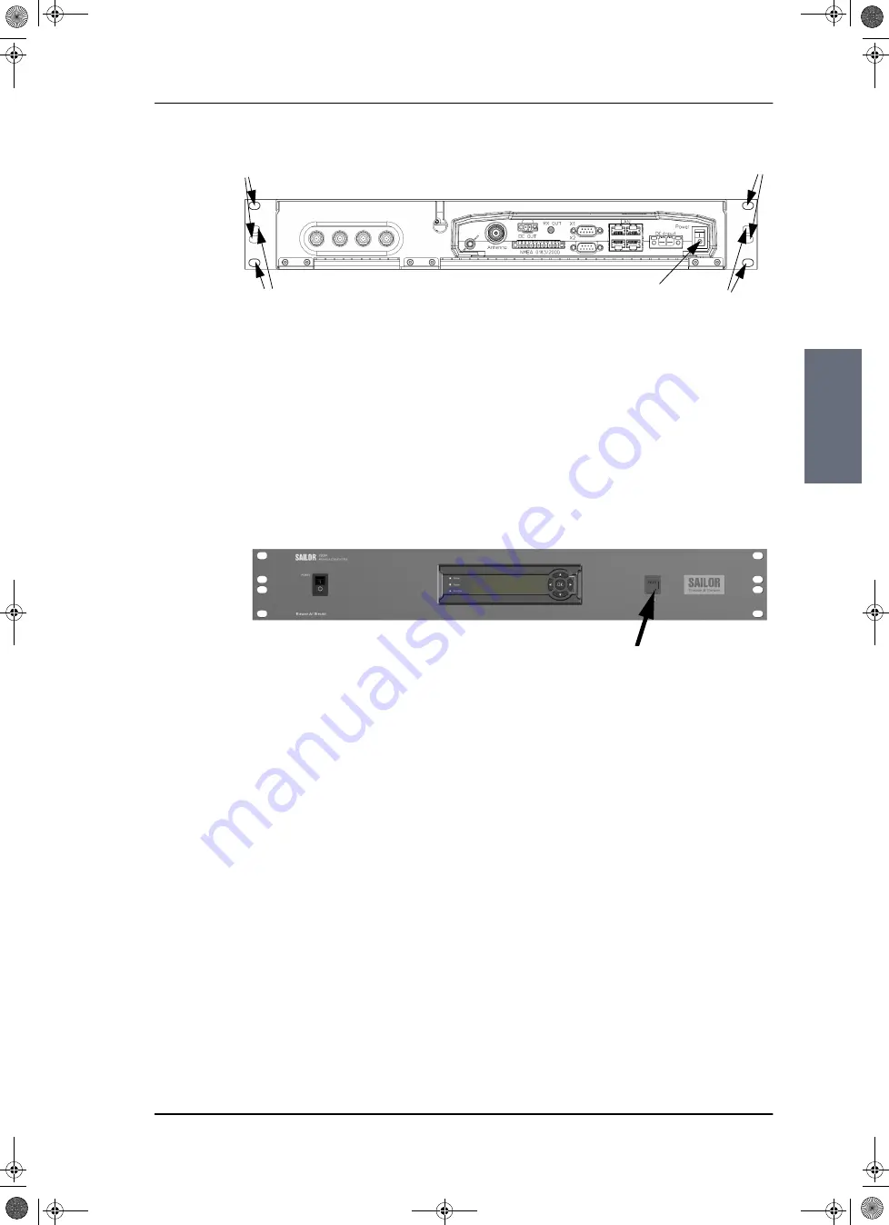
4. Set the On/Off switch at the back of the ACU to On. Then you can use the On/Off
switch at the front panel.
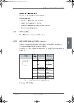
Connectors of the ACU
For a description of the connectors see
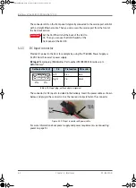
ACU has additionally a LAN connector at the front for accessing the service port from
the ACU front panel.
For information on wiring 24 VDC power see
information about power supply and power requirements see
3.4.2
Grounding the ACU
Make sure that the grounding requirements are met. See the appendix
on page B-1 for details about grounding.
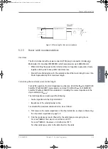
ADU cable
The ADU is connected to the ACU with the ADU cable (coax cable) with an N connector
at both ends. For information on ADU grounding, see
At the ACU end, it is strongly recommended to ground the ADU cable. Use a short cable
from the ACU to a grounding point in the rack and connect the short cable to the ADU
cable at this grounding point, making sure the shield of the connector is properly
connected to the rack.
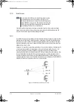
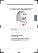
Figure 3-21: ACU, On/off switch at the back
Power
.
TV output
Set to On
ADU
A
A
B
B
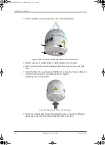
Figure 3-22: ACU, LAN connector at the front: Service port
Service port connected to front
SAILOR100IM.book Page 23 Friday, January 18, 2013 10:28 AM
Summary of Contents for 100
Page 1: ...INSTALLATION MANUAL SAILOR 100 Satellite TV ...
Page 2: ......
Page 8: ...vi 98 136280 B SAILOR100IM book Page vi Friday January 18 2013 10 28 AM ...
Page 141: ...Appendices SAILOR100IM book Page 1 Friday January 18 2013 10 28 AM ...
Page 142: ...SAILOR100IM book Page 2 Friday January 18 2013 10 28 AM ...
Page 178: ...Glossary Glossary 4 98 136280 B SAILOR100IM book Page 4 Friday January 18 2013 10 28 AM ...
Page 185: ......

