Saia-Burgess
Controls Ltd.
Hardware Manual for the PCD3 Series│Document 26/789; Version E 5│31.01.2005
Communication interfaces
4
4-6
RS232 connector as communication interface
4.4
RS232 connector (Port 0) as communication interface and as
connection for programming unit (PCD3.M5xx0 only)
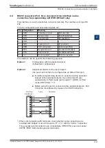
This interface is via a 9-pole D-Sub connector (female). The interface is of type RS
232.
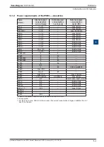
The pin configuration and associated signals are:
Pin Designation
Meaning
1
DCD
Protective ground
[Schutzerde]
2
RXD
Receive data
[Empfangsdaten]
3
TXD
Transmit data
[Sendedaten]
4
DTR
5
SGN
Signal ground
[Signalerde]
6
DSR
PGU connected
[Erkennung PGU]
7
RTS
Request to send
[Sender einschalten]
8
CTS
Clear to send
[Sendebereitschaft]
9
n.c.
Not connected
[Nicht verwendet]
The interface can be used for the following purposes:
Option 1:
Configuration with the desired protocol
(S-Bus PGU configuration)
Option 2:
Assignment (SASI) in the user program
(the port must not then be configured as an S-Bus PGU port)
■ If another programming device is connected during operation
instead of the peripheral device, the unit will switch over
automatically to PGU mode (pin 6 logical “1” (DSR); in PGU
mode: DSR PING = “1”)
■ Before using the port to connect another peripheral device, Port
0 must be reconfigured by means of an SASI instruction.
1
) When communicating with terminals, check whether some connections are
provided with bridges or need to be set to “H” or “L” with the “SOCL” instruction.
It is generally recommended to use a handshake (RTS/CTS) (see also manual
26/795 “PCD7.D23x Series graphic terminals”).
GND
SGN
TX
RX
RTS
1)
CTS
1)
CTS
RTS
TXD
RXD
2
1
4
3
6
5
8
7
PGU-Plug
D-SUB 9 pol.
(female)
Peripheral
9
DCD
Cable
PGD


