Hardware Manual for the PCD3 Series│Document 26/789; Version E 5│31.01.2005
Saia-Burgess
Controls Ltd.
Cabling
Orientation guide
2-5
2
2.3
Cabling
2.3.1 Cable layout
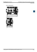
It is recommended to wire the I/O modules from a cable channel mounted above the
module holders.
Cables to connections on the lower part of the module holders (supply, earth) should
preferably be wired from a cable channel below the module holders.
Following these rules will ensure that the LEDs are visible and the bus connections
remain accessible.
2.3.2 Cable routing
● 230V supply lines and signal lines must be laid in separate cables at least 10 cm
apart. Even within the switching cabinet, it is advisable to leave space between
power and signal lines.
● Digital signal / bus lines and analogue signal / sensor lines should be laid in
separate cables
● It is advisable to use shielded cables for analogue signal lines.
● The shield should be earthed at the entry or exit to the switching cabinet. The
shields should be as short as possible and of the largest possible cross-section.
The central earthing point should be > 10 mm² and connected to the PE ground
wire by the shortest route
● The shield is generally connected to one side of the switching cabinet only, unless
there is a potential equalization with significantly lower resistance than the shield
resistance
● Inductivities installed in the same switching cabinet, e.g. contactor coils, should be
provided with suitable suppressors (RC elements)
● Switching cabinet components with high field intensity, e.g. transformers or
frequency inverters, should be shielded with separator plates with a good ground
connection.
Surge protection for long distances or external lines
● Where lines are laid outside the building, or over longer distances, suitable surge
protection measures should be applied. For bus lines in particular, these
measures are essential.
● With lines laid outside, the shield must have adequate current-carrying capacity
and be earthed at both ends.
● The surge conductors should be installed at the input to the switching cabinet.


