Saia-Burgess
Controls Ltd.
Hardware Manual for the PCD3 Series│Document 26/789; Version E 5│31.01.2005
Hardware
Digital I/O cassettes, 230 VAC
5-29
5
5.3
Digital I/O modules, 230 VAC
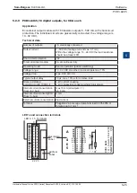
PCD3.A200
4 make contacts 2A
PCD3.A220
6 make contacts 2A
PCD3.A251
6 change-over co 2 make contacts 2 A, connection
via 24-pole cage clamp terminal block
Installation direction
For safety reasons low voltages (up to 50V) and higher voltages (50...250V) must not
be connected to the same module.
If a PCD module is connected to a higher voltage (50...250V), approved components
for this voltage have to be used for all elements which are galvanically connected to
the system.
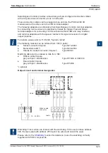
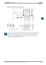
Using higher voltage (50...250V), all connections to the relay contacts must be
connected on the same circuit, i.e. in such a way that they are all protected against
one AC phase by one common fuse. Each load circuit may also be protected
individually.
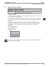
Input signal definition
for 115 – 230 VAC
(PCD3.A200...A220)
I/O modules and I/O connectors must not be removed or plugged in while the PCD is
connected to the power supply.
250VAC
80VAC
40VAC
0VAC
1
0


