COMMAND RANGING & TELEMETRY UNIT CORTEX
Is.Rev.
Date:
© Safran Data Systems
This document is the property of
Safran Data Systems
.
It cannot be duplicated or distributed without expressed written consent.
Page 76
3.3.7.
Ambiguities Solving, I/O Ports & By-passing Capabilities
Color code:
: SPS software task
: Performed by hardware, firmware and/or software
Connector label
on the Interconnection Panel: italic characters.
3.3.7.1.
Low Bandwidth TMU
Viterbi
decoder
Differential
decoder
Frame
Synchronizer
Bi-Phase
decoder
(Option)
BPSK sub-carrier
demodulator
Bit Synchronizer
PM, FM
demodulator
IF inputs
Aux. inputs
Video
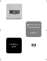
Figure 37: TM Chain : I/O Ports (LBW)
Phase ambiguity solving is by the Frame Synchronizer or by the differential decoder (if PCM code is
NRZ-M or NRZ-S).
External input to the Frame Synchronizer and Viterbi decoder: not available.
Data and Clock output: not available.
Auxiliary inputs: restricted to noise & spurious-free signal with limited amplitude variations
Direct input to PSK Demodulator: set the IF Receiver to « By-pass » mode and select Auxiliary port # 1
or # 2
Direct input to the Bit Synchronizer: set the IF Receiver to « By-pass » mode and the SCF to 0 on the
Telemetry Unit. Select Auxiliary port # 1 or # 2. The signal is expected to have no DC offset at the
AUXILIARY input.