Reverse With Confidence
™
1
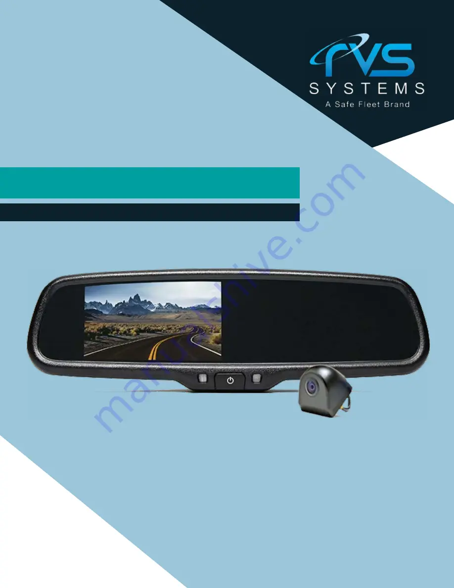
Backup Camera System For Pickup Trucks
RVS-082587
Instruction Manual
RVS Systems, Inc.
© 2016
Page 1: ...ReverseWithConfidence 1 Backup Camera System For Pickup Trucks RVS 082587 Instruction Manual RVS Systems Inc 2016 ...
Page 2: ...e Backup Camera System should not be used as a substitute for the standard rear view mirror or for any other mirror that exists in your vehicle In some jurisdictions it is unlawful for a person to drive a motorvehicleequippedwithaTVviewerorscreenlocatedforwardof the back of the driver s seat or in any location that is visible directly or indirectly to the driver while operating the vehicle Introdu...
Page 3: ...ack up maneuvers or backing intocrosstrafficorpedestrianwalk ways Please always remember the area displayed by the Rear View Camera Systemislimited Itdoesnotdisplay the entire panorama that is behind you USAGE Electric shock or product malfunction may occur if this product is installed incorrectly Use this product within the voltage range specified Failure to do so can cause electronic shock or pr...
Page 4: ... noisy components Werecommenddoingabenchmarktestbeforeinstallation toinsurethatallcomponentsareworkingproperly Step 1 Choose the monitor and camera locations Step 2 Install all cables in vehicle when necessary a 0 8 20mm hole should be drilled for passing camera cable through vehicles walls Install split grommets where applicable Step3 Onceallcablesandwiringhavebeenproperlyrouted perform a system ...
Page 5: ...d keep away from HOT and rotating parts Fasten all cables and secure all excess cable Connect camera to the camera extension cable which runs inside the vehicle Figure 1 2 Wiring Connect the camera to the power harness then plug into the AV2 in put Connect the RED 12V power wire to an ignition power source and the BLACK 12V ground wire to a chassis ground The GREEN wire is the REVERSE trigger wire...
Page 6: ...line is 3M from the back of the car and the yellow line is 6 5 ft The distant red line is 1M from the backside of car while the close red line is 0 4M Both reference lines on the left and right should leave 0 2M space from the car Distance grid line accuracy may vary based on your camera angle Adjust the distance grid lines to fit your application FIGURE1 1 FIGURE1 2 DISTANCE GRID LINES INSTALLATI...
Page 7: ...RVSSystems ReverseWithConfidence 12 13 1 RED Power 2 YELLOW Video 3 GREEN Mirror Normal Imaging 4 WHITE Audio 5 BLACK Ground HOW TO WIRE SPLICING HOW TO WIRE SPLICING FIGURE2 2 FIGURE2 1 ...
Page 8: ... Default Camera to backup camera PAL Auto NTSC CAMERA SPECIFICATIONS Camera PICTURE ELEMENTS GAMMA CORRECTION IMAGE SENSOR LENS VIEW ANGLE SYNC SYSTEM NIGHT VISION POWER SOURCE S N RATIO ELECTRONIC IRIS VIDEO OUTPUT IR SWITCH CONTROL VIBRATION RATING OPERATING TEMPERATURE STORAGE TEMPERATURE MT9V136 250 000 PIXELS R 0 45 TO 1 0 480TV LINES PAL 500 H 582 V NTSC 510 H 492 V 2 1MM 170 INTERNAL SYNCHR...
Page 9: ...t the connection to the camera is tight Verifycameracableispluggedinto port labeled Backup Camera Verify that the green positive triggeronpowerharnessissettore verse power 12v Verify camera is on correct camera input Verify cable is connected to monitor Connect known working camera and cable to monitor NoImageOnScreen TROUBLESHOOTING CAMERA MountingPosition ...
Page 10: ...TH OUR SYSTEMS FUNCTIONS DISCLAIMER ONE YEAR WARRANTY RVS SYSTEMS INC WARRANTS THIS PRODUCT AGAINST MATERIAL DEFECTS FOR A PERIOD OF ONE YEAR FROM DATE OF PURCHASE WE RESERVE THE RIGHT TO REPAIR OR REPLACE ANY SUCH DEFECTIVE UNIT AT OUR SOLE DISCRETION RVS SYSTEMS INC IS NOT RESPON SIBLE FOR A DEFECT IN THE SYSTEM AS A RESULT OF MISUSE IMPROPER INSTALLATION DAMAGE OR MISHANDLING OF THE ELECTRONIC ...
Page 11: ...RVSSystems 20 If you have any questions about this product contact RVSSYSTEMS Inc 1797AtlanticAvenue Brooklyn NY11233 888 881 2601 BetterCameras BetterService IT SOURGUARANTEE ...