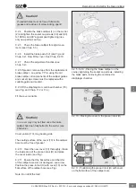
Insert the slide bearing (6)
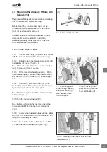
9.3.7 As shown, use a copper hammer and the
tool component (T14) to locate the slide bearing
bushing (6) in the calliper bore (see Fig.).
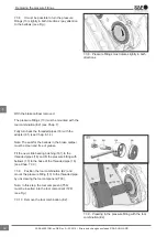
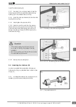
9.3.8 Insert the tool combination (S) into the slide
bearing (6) (see Fig.).
9.3.9 Hand tighten the spindle (T20).
9.3.10 Hold the nut (T14) with the ring spanner
AF24 and use a torque wrench to turn the screw
(T20) and insert the slide bearing (6) as far as it
will go. A maximum torque of 25 Nm must not be
exceeded (see Fig.).
• If the torque during the insertion process
is <4 Nm or >25 Nm, the calliper must be
replaced.
• Do not turn at the nut (T14) as this can cause
the slide bearing (6) to twist.
Caution!
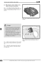
9.3.11 Remove the mounting tool.
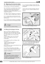
9.4 Installing the bellows (9)
In order to simplify the composition of tools and
components, they are allocated item numbers (see
Chap. 2.1).
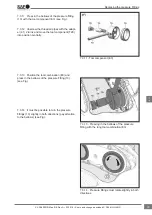
9.4.1 To install the bellows (9), use the tool com-
bination (C) with the tool component (T08).
9.3.7 - Pressing in the slide bearing slightly
9.3.8 - 9.3.10 - Positioning the tool combination (S)
9.4.1 - Tool combination (C)
Repairing the brake calliper bearing
43
en
XL-SA40001RM-en-DE Rev A • 02.2016 • Errors and changes excluded © SAF-HOLLAND


