8. Removing and installing the
brake calliper
In order to simplify the composition of tools and
components, they are allocated item numbers (see
also Chap. 2.1).
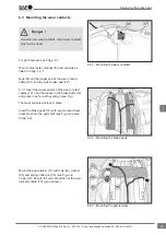
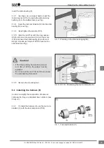
8.0 To fit the cover (10), use the press-in tool
(H), for the cover (68) use the press-in tool (M)
(see Fig.).
8.1 Removing the brake calliper from
the carrier
8.1.1 Remove the brake pads (see Chap. 6.1).
8.1.2 Remove the diaphragm or combined cham-
ber (see Chap. 11.1 or 11.3). If present, remove the
potentiometer cable.
Do not touch electrical contacts on account of
static discharge!
Danger !
Remove the cover (10)
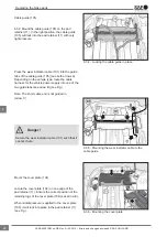
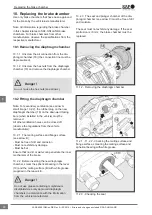
8.1.3 Punch the cover (10) in the centre with a
suitable tool (see Fig.).
The cover (10) can then shift by approx. 10 mm.
Punch the cover (10) in the centre. Do not drive
the levering tool between the calliper bore and
cover (10) as this can damage the bore.
Caution!
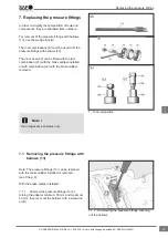
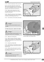
8.1.4 Lever out the cover (10) with a suitable tool
(see Fig.).
Check the bearing area of the calliper bore for
corrosion and repair with a suitable guide and seal
kit if necessary. In the event of severe damage or
corrosion, the brake calliper must be replaced.
8.0 - Press-in tool T27 (M) and T26 (H)
8.1.3 - Punching the centre of the cover with a
suitable tool
8.1.4 - Levering out the cover with a suitable tool
Removing and installing the brake calliper
34
en
XL-SA40001RM-en-DE Rev A • 02.2016 • Errors and changes excluded © SAF-HOLLAND


