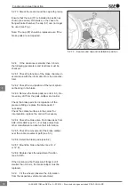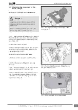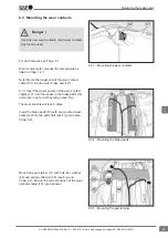
3.2 Functional description
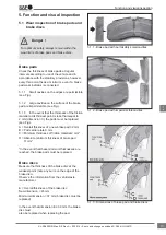
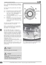
(Sliding calliper brake principle)
Clamping the brake
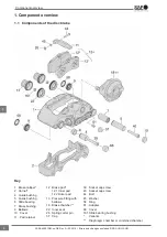
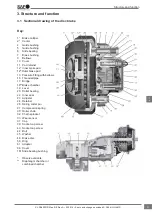
When braking, the piston rod of the combined or
diaphragm chamber (18) presses on the lever (19).
Power is transferred via the roller bearing (20) to
the bridge (17). The clamping force is exerted on
the inner brake pad (121) via the threaded pipes
(16) and pressure fittings (13).
After overcoming the clearance between the brake
pad (121) and brake disc (46), the reaction force
is transferred to the outer brake pad (122) via the
brake calliper (1).
The contact pressure of the brake pads (12) on the
brake disc (46) produces the braking torque for the
wheel.
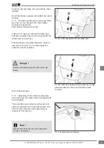
Releasing the brake
If braking pressure is reduced, the compression
spring (27) presses the bridge (17) with threaded
pipes (16) and lever (19) back into the initial
position.
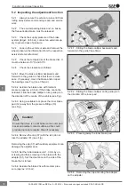
Clearance/wear adjustment device of
the brake
The clearance is the distance between the brake
pad (12) and the brake disc (46). This distance is
required to allow the brake disc (46) to run freely
(unbraked) when in the "brake released" state. If
the clearance is too large, the braking distance may
be extended when braking.
The prescribed clearance has been designed to
compensate for operational influences such as:
• Temperature-dependent changes to component
lengths.
• Viscoelastic effects of the brake pads.
• Manufacturing and axial run-out tolerances of
the disc and hub.
The wear adjustment device ensures a consistent
feed travel by offsetting the abrasion on the brake
pads (12) and the brake disc (46).
With each actuation of the brake, the lever (19)
activates the adjuster (23) after overcoming an
idle stroke representing the design clearance. As
a result, the threaded pipes (16) are pre-turned via
the adjuster (23) and retainer (24) by the amount
by which the prescribed clearance has been
exceeded.
Structure and function
10
en
XL-SA40001RM-en-DE Rev A • 02.2016 • Errors and changes excluded © SAF-HOLLAND

