background image

VISE JAW REPLACEMENT

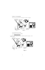
Vise jaws (cartridges) are replaced in pairs as an assembly, a matched set consisting of (one top jaw

and one bottom jaw), you will need two sets for your key machine. You will disassemble and re-

install the old plungers, springs, and screws. Or you can buy a complete set with the plunger, top

jaw, bottom jaw, screws and springs. Simply drop the (cartridges) in place, you will need two

cartridges.

Coat  all  steel  sliding  surfaces  with  a  light  coating  of  grease  when  installing  the  vises.

8.

TOP SHOULDER  KEY GAUGING

Standard cylinder keys should always be top shoulder gauged.  Use the machine’s full-function flip-

up key gauges.  We do not recommend bottom shoulder gauging because key blank manufacturers

do not always maintain a reliable correlation between bottom and top shoulder positions on the key

blanks they make.

Always remember to flip DOWN your key gauges before cutting a key.  Failure to do will prevent your key

machine from cutting the key.

7

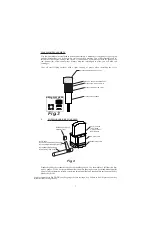
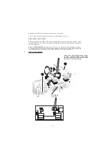
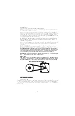
Fig. 4

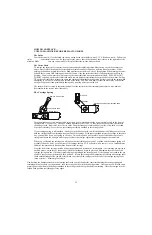
RY10054 Key Gauge

Protector (red)

RY10049Key Gauge Shaft

RY9278 Vinyl Cap (red)

Key Gauge

RY10050 Left-Hand Key Gauge

RY10048 Right-Hand Key Gauge

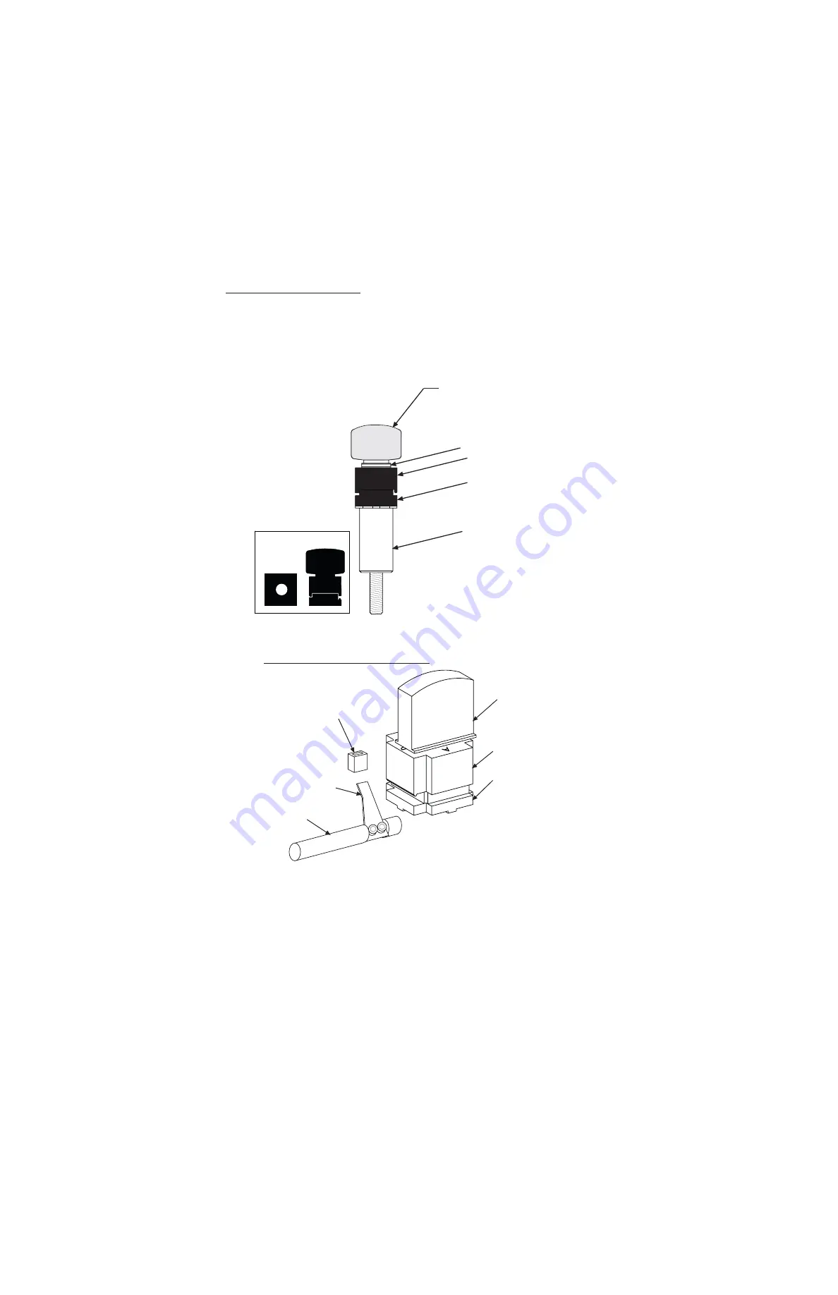
Key Vise Knob

(

with)

 RY82

3-piece Thrust

Bearing Assy.

Top 4-way Jaw

Bottom 4-way Jaw

Fig.3

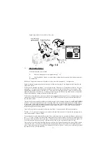
CLAMPS MORE KEYS

NEW 4-WAY VISES

A

B

C

D

RY20080 KNOB WITH SHAFT ASSY.

RY82 3-PC THRUST BEARING ASSY.

RY20089 TOP VISE, JAW 4-WAY

RY20047 BOTTON VISE, 4-WAY

RY20046 VISE PLUNGER

Summary of Contents for RY456

Page 1: ...TAN KEYS BUILT IN MICRO ADJUST STYLUS Rytan Products are Designed and Manufactured in the U S A RYTAN INC 1648 W 134th St Gardena CA 90249 800 447 9826 310 212 6002 NEW 4 WAY JAWS CLAMPS MORE KEYS 2 W...

Page 2: ...AUGING 9 CLAMPING KEYS 10 BEST and TIP GAUGING 11 RELEASING THE CARRIAGE 12 CUTTER SHAFT LOCK 13 REMOVING REPLACING CUTTER 14 DEPTH ADJUSTMENT 15 SPACE ADJUSTMENT 16 KEY GAUGE ADJUSTMENT 17 CARRIAGE O...

Page 3: ...Read the owner s manual carefully Learn its applications and limitations as well as specific operational hazards peculiar to this machine B Guard against electrical shock by preventing body contact wi...

Page 4: ...ing Do not attempt to remove key blank or key blank material while cutter is rotating T Never use machine in an explosive atmosphere For example if your machine is in a service vehicle with a fuel lea...

Page 5: ...You must loosen the painted key clamping knobs a few turns turn the vise and retighten Make sure your vise jaws are clean with no chips in the way and as you secure the vise jaw on to your key be sure...

Page 6: ...the key blade For these keys you can flip your vise jaws to B Loosen the vise jaw a few turns flip the vise jaws to B and retighten the large painted knob You must do both vise jaws for this to work Y...

Page 7: ...the machine s full function flip up key gauges We do not recommend bottom shoulder gauging because key blank manufacturers do not always maintain a reliable correlation between bottom and top shoulder...

Page 8: ...oor do not have a top shoulder to gauge from Open the vise jaws A vises ONLY enough to slide in the thinnest part of the key See Fig 5 6 Slide in the key blank and allow the full thickness ridge of th...

Page 9: ...o actions With your right hand push down gently on the carriage s large teardrop knob just enough to push the carriage down a small distance While holding the carriage down reach around with your thum...

Page 10: ...using a 1 wrench to remove the cutter 10 New Cutter will cut straight on left side of key cut Adjustable Stylus 0005 one half thousanth INCH NEW 4 WAY VISES CLAMPS MORE KEYS 2 WAY 3 WAY 1 WAY 4 WAY Po...

Page 11: ...e finished reinstalling the cutter wheel Pulling UP on the cutter shaft lock releases the cutter and the cutter shaft from the locked position Failure to unlock the cutter when attempting to cut a key...

Page 12: ...e cutter wheel and Left Hand Nut DON T OVERTIGHTEN the cutter wheel nut The Left Hand Nut is self tightening as you use it Overtightening the cutter wheel nut may make it harder to remove later and ma...

Page 13: ...blade The reason for turning the cutter backwards is to prevent any cutter teeth from removing material off the key blank s blade before you make your adjustments Turning the cutter backwards will bum...

Page 14: ...w and throw off your adjustment There should be NO key blanks in the left vise jaw for this part of the procedure DO NOT FORGET to flip down your key gauges Failure to do so may result in damage to th...

Page 15: ...n Hex Wrench IMPORTANT Verify that your depth adjustment is correct and readjust if necessary Refer back to Depth Adjustment if necessary Spacing Adjustment is now complete IMPORTANT Verify that your...

Page 16: ...is 20 which is approximately 12 thousands of an inch per turn Tighten the 7 16 Hex Jam Nut on the slotted screw stud use moderate tightness After tightening the 7 16 not check the gap between the styl...

Page 17: ...r WD 40 as a rust preventative in addition to the number 30 non detergent motor oil If you only use LPS 1 or WD 40 as your machine s only lubricant you will eventually damage the machine These lubrica...

Page 18: ...Cutter wheel may be dull This can cause the key to try to float and not cut deep enough in the deepest cuts Replace or resharpen the cutter 2 Carriage spring may be weak or adjusted to light Replace t...

Page 19: ...rape material from the key blank The solution is to lightly blunt the sharp edge of the stylus This has to be done carefully because if the edge of the stylus is blunted to much you will narrow the wi...

Page 20: ...on these premium blanks a Duplicate them a little slower Racing through the job especially in large rekeying jobs will put more wear on the cutter wheel than going a little slower The machine s high...

Page 21: ...it s not in use put a piece of heavy cardboard a small piece of wood or even a piece of indoor outdoor carpet WHEN DO I REPLACE a Replace the cutter wheel when deburring the key seems to take longer t...

Page 22: ...y and pull out the stick shift lever and drive shaft assembly Leave the two piece linkage assembly attached to the carriage shaft If your carriage spring is still attached firmly grasp the linkages wi...

Page 23: ...of 1 diameter hard wood dowel purchased from your local hardware store Cut off a piece about 6 long and use it to pound out the bearings with a hammer Cut off a piece of 1 diameter hard wood dowel ab...

Page 24: ...e carriage Why Didn t We Use Gears to Drive the Carriage Left and Right Gears are pumps on a key machine they pump dirt and key cuttings Gears get crunchy our linkages do not Why Aren t the Vise Jaws...

Page 25: ...loped in 1998 In late 1984 there was a problem with the 1984 1 2 Ford double sided ignition locks with a side bar The only practical way to get through the lock was to drill the side bar or use try ou...

Reviews: