background image

© All rights reserved to 

Ruptela UAB 


P a g e

 | 

13


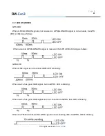
When the FM-Pro3 terminal has GSM signal and it is sending data via GPRS, LED is blinking: 


Peripheral LED 

To the FM-Pro3 terminal can be attached up to three peripheral interfaces. So there are 3 

different types of blinking when one or other peripheral is connected. 

When there is no peripheral attached, LED will not blink at all: 


When there is 1 out of 3 peripheral interfaces connected, the peripheral LED is blinking: 


When there are 2 out of 3 peripheral interfaces connected, peripheral LED is blinking: 


When there are 3 out of 3 peripheral interfaces connected, Peripheral LED is blinking: 


FM-

Pro3 

Summary of Contents for ECO3

Page 1: ... All rights reserved to Ruptela UAB User Manual FM ECO3 PRO3 TCO3 Version 7 Last update 2013 08 27 ...

Page 2: ... PAGE 9 2 5 TECHNICAL FEATURES PAGE 10 2 6 FM PRO3 DIMENSIONS PAGE 11 2 7 LED STATUSES PAGE 12 13 2 8 PINOUT CONNECTION USB PAGE 14 15 2 9 SPECIAL FEATURES PAGE 15 2 10 QUALIFICATION AND CERTIFICATION PAGE 16 3 FM ECO3 PAGE 17 24 3 1 BASIC DESCRIPTION PAGE 17 3 2 PACKAGE CONTENTS PAGE 18 3 3 ADDITIONAL ACCESSORIES PAGE 18 3 4 BASIC CHARACTERISTICS PAGE 19 3 5 TECHNICAL FEATURES PAGE 20 3 6 FM ECO3...

Page 3: ...ATION AND CERTIFICATION PAGE 34 5 INSTALLATION AND CONFIGURATION INSTRUCTIONS PAGE 35 5 1 MODULE INSTALLATION PAGE 35 36 5 2 DEVICE CONNECTION TO A PERSONAL COMPUTER PAGE 37 5 2 1 SYSTEM REQUIREMENTS PAGE 37 5 2 2 PREPARATION FOR CONNECTION PAGE 37 5 2 3 DRIVER INSTALLATION PAGE 38 42 5 3 CONFIGURATOR PAGE 42 5 3 1 INTERFACING TO COM PORT PAGE 42 44 5 3 2 GLOBAL PARAMETER CONFIGURATION PAGE 44 46 ...

Page 4: ... between different pieces of equipment Simplified RS232 has only Rx and Tx lines RS485 connection standard between different multiple pieces of equipment physically connected with Port A where Simplified RS232 is placed We can configure a device to use RS485 or RS232 as Port A LED Light Emitting Diode CAN bus FMS standard interface I O Inputs Outputs OBD On Board Diagnostics socket K_Line L_Line P...

Page 5: ...ent produces interference that may affect other devices which are placed nearby The terminal can be installed or dismounted only by qualified personnel The terminal must be firmly fastened in the predefined location Predefined location is explained in the mounting instructions The programming must be performed using a 2nd safety class of PCs with autonomic power supply Be sure that the terminal is...

Page 6: ...ese instructions carefully and follow them strictly before operating the device The terminal is supplied from a car battery with these ratings 12 24V 1A 500mA The allowed voltage range for the battery is 10 32V DC To avoid mechanical damage it is advised to transport the FM terminal in an impact proof package Before connecting the wires with 14 PINs plug to the vehicle ensure that 10 PINs plug is ...

Page 7: ...t FM Pro3 has additional inputs and outputs which let control and monitor other remote objects 1 Wire interface for Dallas Digital Thermometer or I Button Reader and CAN bus interface are integrated for data acquisition of trucks FMS data interface It also has 2 simplified RS232 ports and one RS485 to connect additional equipment such as Personal Navigation Device digital fuel level sensor or othe...

Page 8: ...ified RS232 RS485 and K_line L_line connection 2 3 ADDITIONAL ACCESSORIES There are a few standard accessories available for FM Pro3 that are not included in the package Analog Temperature sensor 1 Wire Digital Temperature Sensor DS18B20 DS18S20 I Button Note the manufacturer does not supply a SIM card in the package which is necessary for connection to the GSM network SIM card can be obtained fro...

Page 9: ... e 9 2 4 BASIC CHARACTERISTICS Inputs Outputs IO1 10 pin 2x5 plug IO2 14 pin 2x7 plug Paired connection scheme Other Inputs Outputs are not paired Also two spare Chassis pins can be paired with any I O they are only for easier mounting FM Pro3 ...

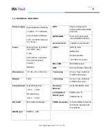
Page 10: ...ed into internal battery module SMD 2A LED s GPS fix LED GSM LED Peripheral LED All LED s are green Mini USB Mini USB socket SIM SIM card holder with lock Dimensions 111 25 x 75 x 25 2 mm 10 pin plug For ex Tyco multi lock 4 794619 0 socket Weight 140g 14 pin plug For ex Tyco multi lock 4 794619 4 socket Temperatures Operational temp 35 C 55 C Storage temp 40 C 65 C Housing Material UL94 HB Plasti...

Page 11: ... All rights reserved to Ruptela UAB P a g e 11 2 6 FM PRO 3 DIMENSIONS FM Pro3 ...

Page 12: ... GPS LED is blinking as follows When accurate GPS GLONASS signal is received the GPS LED is blinking as follows GSM LED When GSM signal is not received GSM LED is blinking as follows When device has a good GSM signal but no GPRS LED is blinking as follows When device has good GSM signal and it is connected to GPRS then LED is blinking as follows FM Pro3 ...

Page 13: ...rfaces So there are 3 different types of blinking when one or other peripheral is connected When there is no peripheral attached LED will not blink at all When there is 1 out of 3 peripheral interfaces connected the peripheral LED is blinking When there are 2 out of 3 peripheral interfaces connected peripheral LED is blinking When there are 3 out of 3 peripheral interfaces connected Peripheral LED...

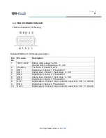
Page 14: ...ne SAE J1939 CAN interface L_Line channel diagnostics 10 CAN L SAE J1939 CAN interface Low channel 11 K_Line SAE J1939 CAN interface K_Line channel diagnostics 12 Chassis The frame or chassis of a car 13 PORTA 485A RS 485 differential signaling line A 14 PORTA 485B RS 485 differential signaling line B TRRS connector is used for connecting speaker and microphone to FM device Communication is half d...

Page 15: ...32V 250 mA 9 DIN 4 Digital input channel 4 Threshold 4V 10 OUT 2 Digital output Channel 2 Open collector output Max 32V 250 mA USB 2 9 SPECIAL FEATURES Any element event triggers external sensor input speed temperature etc Smart profile switching GSM operator or any element depended Highly configurable data acquisition and sending Real time process monitoring Authorized number list for remote acce...

Page 16: ...of the Directive Essential Requirements Conformed Specifications Standards Safety R TTE Article 3 1 a EN 60950 1 2006 A11 2009 EMC R TTE Article 3 1 b EN 301 489 1 V1 6 1 EN 301 489 7 V1 3 1 Radio Spectrum R TTE Article 3 2 EN 301 511 v9 0 2 Environmental testing Part 2 64 Tests Test Fh Vibration broadband random and guidance IEC 60068 2 64 2008 LST EN 60068 2 64 2008 FM Pro3 ...

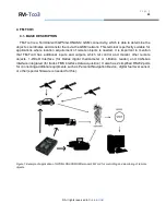
Page 17: ... transfer them via the GSM network This terminal is perfectly suitable for applications where location acquirement of remote objects is needed It is important to mention that FM Eco3 has additional inputs and outputs which let control and monitor other remote objects Figure1 Example of application of GPS GLONASS GSM terminal FM Eco3 for controlling and monitoring of remote objects FM Eco3 ...

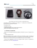
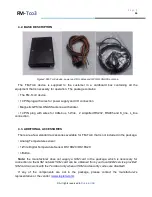
Page 18: ...S GLONASS antenna with sticker 3 3 ADDITIONAL ACCESSORIES There are a few standard accessories available for FM Eco3 that are not included in the package Analog Temperature sensor Note the manufacturer does not supply a SIM card in the package which is necessary for connection to the GSM network SIM card can be obtained from your local GSM service provider SIM card can work with the terminal only ...

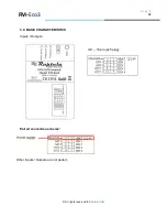
Page 19: ... All rights reserved to Ruptela UAB P a g e 19 3 4 BASIC CHARACTERISTICS Inputs Outputs IO1 10 pin 2x5 plug Paired connection scheme Other Inputs Outputs are not paired FM Eco3 ...

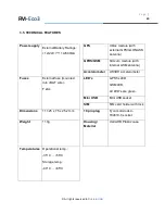
Page 20: ...internal GSM antenna Accelerometer LIS3DH accelerometer Fuses External fuse mounted into BAT wire F 2AL LED s GPS fix LED GSM LED All LED s are green Mini USB Mini USB socket SIM SIM card holder with lock Dimensions 111 25 x 75 x 25 2 mm 10 pin plug Tyco multi lock 4 794619 0 socket Weight 110g Housing Material UL94 HB Plastic case Temperatures Operational temp 35 C 55 C Storage temp 40 C 65 C FM ...

Page 21: ... All rights reserved to Ruptela UAB P a g e 21 3 6 FM ECO3 DIMENSIONS FM Eco3 ...

Page 22: ...lows When accurate GPS GLONASS signal is received the GPS LED is blinking as follows GSM LED When GSM signal is not received GSM LED is blinking When device has good GSM signal but no GPRS LED is blinking When device has good GSM signal and it is connected to GPRS then LED is blinking When the FM Eco3 terminal has GSM signal and it is sending data via GPRS LED is blinking FM Eco3 ...

Page 23: ...is The frame or chassis of a car 3 DIN 1 Digital input channel 1 Threshold 4V 4 AIN 1 Analog input channel 1 Input range 0 30V 5 DIN 2 Digital input channel 2 Threshold 4V 6 AIN 2 Analog input channel 2 Input range 0 30V 7 DIN 3 Digital input channel 3 Threshold 4V 8 OUT 1 Digital output Channel 1 Open collector output Max 32V 250 mA 9 DIN 4 Digital input channel 4 Threshold 4V 10 OUT 2 Digital ou...

Page 24: ...r Mini USB port Configuration update via GPRS SMS or Mini USB port TCP IP or UDP IP protocol support 16 000 record storing 3 10 QUALIFICATION AND CERTIFICATION The FM Eco3 terminal complies the essential requirements detailed in the following Articles of the Directive Essential Requirements Conformed Specifications Standards Safety R TTE Article 3 1 a EN 60950 1 2006 A11 2009 EMC R TTE Article 3 1...

Page 25: ... mention that FM Tco3 has additional inputs and outputs which let control and monitor other remote objects 1 Wire interface for Dallas digital thermometer or I Button reader and CAN bus interface integrated for trucks FMS interface data acquisition It also has 2 simplified RS232 ports for connecting additional equipments such as Personal Navigation Device digital fuel level sensor or other special...

Page 26: ...lified RS232 RS485 and K_line L_line connection 4 3 ADDITIONAL ACCESSORIES There are a few standard accessories available for FM Tco3 that is not included in the package Analog Temperature sensor 1 Wire Digital Temperature Sensor DS18B20 DS18S20 I Button Note the manufacturer does not supply a SIM card in the package which is necessary for connection to the GSM network SIM card can be obtained fro...

Page 27: ...e 27 4 4 BASIC CHARACTERISTICS Inputs Outputs IO1 10 pin 2x5 plug IO2 14 pin 2x7 plug Paired connection scheme Other Inputs Outputs are not paired Also two spare Chassis pins can be paired with any I O they are only for easier mounting FM Tco3 ...

Page 28: ...ed into internal battery module SMD 2A LED s GPS fix LED GSM LED Peripheral LED All LED s are green Mini USB Mini USB socket SIM Sim card holder with lock Dimensions 111 25 x 75 x 25 2 mm 10 pin plug For ex Tyco multi lock 4 794619 0 socket Weight 140g 14 pin plug For ex Tyco multi lock 4 794619 4 socket Temperatures Operational temp 35 C 55 C Storage temp 40 C 65 C Housing Material UL94 HB Plasti...

Page 29: ... All rights reserved to Ruptela UAB P a g e 29 4 6 FM TCO3 DIMENSIONS FM Tco3 ...

Page 30: ... GPS LED is blinking as follows When accurate GPS GLONASS signal is received the GPS LED is blinking as follows GSM LED When GSM signal is not received GSM LED is blinking as follows When device has a good GSM signal but no GPRS LED is blinking as follows When device has good GSM signal and it is connected to GPRS then LED is blinking as follows FM Tco3 ...

Page 31: ...es attached So there are 3 different types of blinking when one or other peripheral is connected When there is no peripheral attached LED will not blink at all When there is 1 out of 3 peripheral interfaces connected Peripheral LED is blinking When there are 2 out of 3 peripheral interfaces connected Peripheral LED is blinking When there are 3 out of 3 peripheral interfaces connected Peripheral LE...

Page 32: ...ne SAE J1939 CAN interface L_Line channel diagnostics 10 CAN L SAE J1939 CAN interface Low channel 11 K_Line SAE J1939 CAN interface K_Line channel diagnostics 12 Chassis The frame or chassis of a car 13 PORTA 485A RS 485 differential signaling line A 14 PORTA 485B RS 485 differential signaling line B TRRS connector is used for connecting speaker and microphone to FM device Communication is half d...

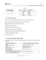
Page 33: ... 8 OUT 1 Digital output Channel 1 Open collector output Max 32V 250 mA 9 DIN 4 Digital input channel 4 Threshold 4V 10 OUT 2 Digital output Channel 2 Open collector output Max 32V 250 mA USB Pin No Pin name Description 1 VBUS Power 2 D Data 3 D Data 4 ID NC 5 GND Ground 4 9 SPECIAL FEATURES Any element event triggers external sensor input speed temperature etc Smart profile switching GSM operator ...

Page 34: ...removed total distance trip distance speed RPM 4 10 QUALIFICATION AND CERTIFICATION The FM Tco3 terminal complies the essential requirements detailed in the following Articles of the Directive Essential Requirements Conformed Specifications Standards Safety R TTE Article 3 1 a EN 60950 1 2006 A11 2009 EMC R TTE Article 3 1 b EN 301 489 1 V1 6 1 EN 301 489 7 V1 3 1 Radio Spectrum R TTE Article 3 2 ...

Page 35: ... fixed to the surface Please avoid mounting module near the metal surface or cables see the picture below Wrong module mounting may be the cause of module malfunction Module cannot be fixed to heat emitting or moving parts SIM card should be inserted in the module while the connector is plugged off while module has no power Module must be fitted with double sided stick tape FM Manual ...

Page 36: ...6 GPS GLONASS antenna connection It is recommended to place GPS GLONASS antenna behind the dashboard as close to the window as possible A good example of GPS GLONASS antenna placement is displayed in a picture below area colored in blue FM Manual ...

Page 37: ...ows XP or Microsoft Windows Vista or Microsoft Windows 7 32 bit and 64 bit Microsoft NET framework 4 available as a free download from http www microsoft com downloads en details aspx FamilyID 9cfb2d51 5ff4 4491 b0e5 b386f32c0992 5 2 2 PREPARATION FOR CONNECTION Before connecting FM Terminal to PC please check if you have the latest configuration software You can download it from here ftp dev rupt...

Page 38: ...first time a notification should pop up that new hardware was found and configuration window is shown Fig 5 2 3 1 Select No not this time and click button Next 2 In the next window select Install from a list or specific location Advanced Fig 5 2 3 2 Fig 5 2 3 2 Driver installation FM Manual Fig 5 2 3 1 Driver installation ...

Page 39: ... search and click Browse and navigate to folder where configuration software is saved i e F FM3 configurator 00 01 15 then click next Fig 5 2 3 3 4 Then driver installation should proceed If asked click Continue Anyway Fig 5 2 3 4 Fig 5 2 3 4 Driver installation Fig 5 2 3 3 Driver installation FM Manual ...

Page 40: ...ctions 1 Click finish and go to Device Manager 2 In device manager go to Ports COM LPT 3 Expand section then right click on FM type device COMXX 4 Select Disable Fig 5 2 3 6 5 When asked for confirmation click Yes 6 Then again right click on FM type device COMXX 7 Select Enable Fig 5 2 3 7 8 Driver now should be completely installed and ready to use Fig 5 2 3 8 Fig 5 2 3 5 Driver installation FM M...

Page 41: ... All rights reserved to Ruptela UAB P a g e 41 Fig 5 2 3 6 Driver installation Fig 5 2 3 7 Driver installation FM Manual ...

Page 42: ...COM PORT In the main view upper left corner there is a drop box which contains COM ports list You should select port corresponding to your device you can check it in Device manager and click Connect button If connection is successful Connect button changes into Disconnect and in the bottom of the main view there should be information available about software hardware and IMEI number Fig 5 3 1 2 Al...

Page 43: ... 3 1 3 Device type selection drop box If you want to enter Diagnostics tool you need to click on COM port i e and then press Ctrl Alt D buttons A new button Diagnostics will appear in the left bottom corner You will need to connect to exact COM port there After that you will be able to see Voltage of analog inputs Voltage of internal battery and power supply Charge current Status of digital inputs...

Page 44: ...ion 5 3 2 GLOBAL PARAMETER CONFIGURATION Global parameters are parameters which apply to the system in general Global parameters are constant and do not change while the device is working unless they are configured by user Fig 5 3 2 1 Fig 5 3 2 1 Global parameter view FM Manual ...

Page 45: ...ies to send data to IP1 if it is valid If first 5 tries were unsuccessful device tries to connect IP2 for five times If tries are unsuccessful gets back to first IP When connection occured means that device got a response to it s sent packet device sets this IP IP1 or IP2 as a primary IP So all further packets are sent to this primary IP After firmware or configuration file update after restart pr...

Page 46: ...nt with password if device is protected Leave it blank if you are not using this feature Fig 5 3 2 2 SMS numbers and password Warning If you leave authorised number and password fields empty then 3rd parties who know SIM card number will be able to change configuration or do any other action with the device ECO driving only for PRO3 and TCO3 devices group of settings where you can choose profiles ...

Page 47: ... Link Timeout period expires For advanced sending rules user can use timetable by enabling it and configuring click Timetable In timetable a week is divided into periods of 10 minutes Fig 5 3 3 2 User can select day of week and exact time when GPRS sending is allowed In order to select deselect whole hour user should click on row header cell It is possible to configure timetable and copy it to ano...

Page 48: ... All rights reserved to Ruptela UAB P a g e 48 Fig 5 3 3 2 Timetable view FM Manual ...

Page 49: ...n parameters bottom middle Fig 5 3 3 3 are used to set up record collection rules Fig 5 3 3 3 Data collection option view Time without engine sets maximum period within which device must make records It is mostly used to make records when device is not moving so this parameter should not be longer than Time with engine in coefficients section Engine selection defines how FM device detects whether ...

Page 50: ...first profile As soon as registered to a GSM network device checks up operator lists from 1st profile to 4th and if it finds GSM operator code http en wikipedia org wiki Mobile_Network_Code in that list it jumps to corresponding profile If no matching profile list is found device jumps to first profile with empty operator list so it is recommended to leave 4th profile with empty operator list If t...

Page 51: ...ction to measured value When IO event occurs device makes a record into its memory with measured values date time and location IO events can initiate GPRS session Also IO can change device operation by switching profile You can select up to 110 IO events Fig 5 3 3 6 IO events settings buttons To add IO to data record and create IO event Fig 5 3 3 7 Select space for IO If it is Disabled then it is ...

Page 52: ...ent generation only include value to record Hysteresis event generation defined by Level and Delta Change event generated when measured property changes that means its value is different from previous registered value Select whether to always include value to record or only when event is generated Select priority Low do not start GPRS session after event and send data according to timing defined i...

Page 53: ...rement units analogue inputs temperature measurements etc while others are defined in specific standards as CAN FMS 2 0 CANbus parameters settings settings are located in the bottom right corner on the main view and are accessible by clicking Options button Fig 5 3 3 6 For different vehicles different settings must be used Different devices supports different type of CANbus PRO3 supports only FMS ...

Page 54: ... All rights reserved to Ruptela UAB P a g e 54 Fig 5 3 3 9 FMS standard CANbus settings Fig 5 3 3 10 LCV CANbus settings Fig 5 3 3 11 LCV CANbus settings FM Manual ...
Page 55: ...nother CANbus parameter from Board computer Mostly this is used when OBD connection is used or some extra third part CANbus converter between vehicle and PRO3 TCO3 devices is connected 5 3 4 SAVING AND LOADING CONFIGURATION Fig 5 3 4 1 Configuration saving scheme In the main view upper left corner there are Save CFG and Load CFG buttons which save and load configuration files In order to save file...

Page 56: ... 3 4 2 Configuration loading scheme There s an ability to save and load only a difference in configurations When loading difference new parameters will be applied from loaded configuration fig 5 3 4 3 Fig 5 3 4 3 Saving and loading differences FM Manual ...
Page 57: ... will see progress bar active Analogue actions should be done to send configuration to device All profiles are saved and loaded from device at once Report will be written at the bottom of main view after action Possible reports Configuration Sent Successfully Configuration Send Error Configuration Received Successfully Configuration Receiving Error If you receive error report retry your last actio...

Page 58: ... notification will pop up on the bottom of the device and LEDs will glow continuously for about a minute Firmware update takes up to 5 minutes so device must be powered up during that time Device is completely ready to use when LEDs start blinking Fig 5 4 2 Firmware update scheme FM Manual ...

Page 59: ...ssed by 0 4 steps 128 51 pedal pressed to the middle CAN ambient air temperature 2 0 65535 0 03125 C Bit gain 273 C offset 9376 20 C CAN at least one PTO engaged 1 0 3 0 No PTO drive is engaged 1 At least one PTO drive is engaged 2 Error 3 Not available CAN axle location 1 0 15 Defined in FMS 2 0 standard CAN axle weight 2 0 65535 0 5 kg Bit gain 20000 10000kg CAN brake switch 1 0 1 0 pedal releas...

Page 60: ... first driver ID 16 Driver ID Card Number CAN fuel level1 1 0 255 0 4 Bit gain 128 51 CAN fuel rate 2 0 64255 0 05L h per bit 0 to 3212 75L h 600 30L h CAN high resolution engine total fuel used 4 0 4211081215 0 001 L bit 0 to 4211081 215 L 1000000 1000L CAN high resolution total vehicle distance 4 0 4294967295 5 m Bit gain 10000 50000m CAN instantaneous fuel economy 2 0 64256 1 512 km L per b 0 t...

Page 61: ... CAN SW version supported 4 Defined in FMS 2 0 standard CAN tacho direction indicator 1 0 1 0 Forward 1 Reverse CAN tacho driver 1 time related status 1 0 15 0 normal 1 15 min bef 4 h 2 4 h reached 3 15 min bef 9 h 4 9 h reached 5 15 min bef 16 h 6 16h reached 14 Error 15 not available CAN tacho driver 2 card 1 0 1 0 Card not present 1 Card present CAN tacho driver 2 time related status 1 0 15 0 n...

Page 62: ...e 1 0 7 0 Rest 1 Driver available 2 Work 3 Drive 6 Error 7 not available CAN tacho handling information 1 0 1 0 no handling information 1 handling information CAN tacho vehicle motion 1 0 1 0 Vehicle motion not detected 1 vehicle motion detected CAN tachograph performance 1 0 1 0 Normal performance 1 Performance analysis CAN tachograph vehicle speed 2 0 65535 1 256km h Bit gain 15360 60km h CAN ti...

Page 63: ...e 1023 full 0 empty Digital Fuel Sensor A4 2 0 1023 Relative to size 1023 full 0 empty Digital Fuel Sensor A5 2 0 1023 Relative to size 1023 full 0 empty Digital Fuel Sensor A6 2 0 1023 Relative to size 1023 full 0 empty Digital Fuel Sensor A7 2 0 1023 Relative to size 1023 full 0 empty Digital Fuel Sensor A8 2 0 1023 Relative to size 1023 full 0 empty Digital Fuel Sensor A9 2 0 1023 Relative to s...

Page 64: ...1 high level on input DIN2 1 0 1 0 low level on input 1 high level on input DIN3 1 0 1 0 low level on input 1 high level on input ECO brake counter 1 0 255 Braking event counter ECO cruise control timer 4 0 4294967295 Split parameter for time when cruise control was on and cruise control should be on ECO engine on timer 2 0 65535 Time when engine was on ECO extreme and harsh brake counter 1 0 255 ...

Page 65: ... 65535 Depends on Counter Fuel Counter 2 2 0 65535 Depends on Counter GPS speed 1 0 255 Value km h GSM operator 4 0 4294967295 Unique Mobile operator code http en wikipedia or g wiki Mobile_Netwo rk_Code iButton ID 8 Unique iButton ID Ignition DIN4 1 0 1 0 low level on input 1 high level on input Movement sensor 1 0 1 0 No motion detected 1 Motion detected Modem temperature 1 40 90 C PCB temperatu...

Page 66: ...se plate number TCO second driver card 1 0 1 0 Card not present 1 Card present TCO second driver ID 16 Driver ID Card Number TCO second driver state 1 0 7 0 Rest 1 Driver available 2 Work 3 Drive 6 Error 7 not available TCO first driver card 1 0 1 0 Card not present 1 Card present TCO first driver ID 16 Driver ID Card Number TCO first driver state 1 0 7 0 Rest 1 Driver available 2 Work 3 Drive 6 E...

Page 67: ... 2001 1wire bus short circuit 2002 CRC error 2003 no sensors 2004 abnormal temperature Temperature sensor0 ID 8 Unique temperature sensor ID Temperature sensor1 2 550 1250 0 1 C Bit gain 200 20 C 2001 1wire bus short circuit 2002 CRC error 2003 no sensors 2004 abnormal temperature Temperature sensor1 ID 8 Unique temperature sensor ID Temperature sensor2 2 550 1250 0 1 C Bit gain 200 20 C 2001 1wir...

Reviews: