background image

Hardware Installation and Reference Guide 


Appendix A Connectors and Media 

22 

Appendix A Connectors and Media 

1000BASE-T/100BASE-TX/10BASE-T


The  1000BASE-T/100BASE-TX/10BASE-T  is  a  10/100/1000  Mbps  self-adaptive  port  that  supports  auto 

MDI/MDIX Crossover. 

Compliant with IEEE 802.3ab, 1000BASE-T requires Category 5e 100-ohm UTP or STP (STP is recommended) 

with a maximum distance of 100 meters (328 feet). 

The 1000BASE-T port requires all four pairs of wires be connected for data transmission. 

Table 8-1 

1000BASE-T Connection 


10BASE-T uses Category 3, 4, 5 100-ohm UTP/STP and 1000BASE-T uses Category 5 100-ohm UTP/STP for 

connections. 

Both support a maximum length of 100 meters 

(328 feet)

. The following table shows 100BASE-

TX/10BASE-T pin assignments.


Table 8-2 

100BASE-TX/10BASE-T Pin Assignments 

Pin 

Socket 

Plug 

Input Receive Data+ 

Output Transmit Data+ 

Input Receive Data- 

Output Transmit Data- 

Output Transmit Data+ 

Input Receive Data+ 

Output Transmit Data- 

Input Receive Data- 

4, 5, 7, 8 

Not Used 

Not Used 


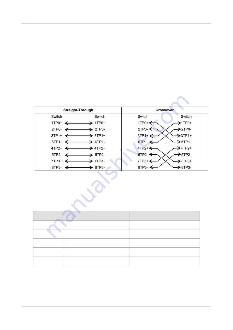
The following table shows the wiring of straight-through and crossover cables for 100BASE-TX/10BASE-T. 

Summary of Contents for Reyee RG-EG105GWT

Page 1: ...Ruijie Reyee RG EG105GW T Router Hardware Installation and Reference Guide Document Version V1 0 Date 2022 08 22 Copyright 2022 Ruijie Networks...

Page 2: ...purchase are subject to commercial contracts and terms Some or all of the products services or features described in this document may not be within the scope of your purchase or use Unless otherwise...

Page 3: ...scribed as below Danger An alert that calls attention to safety operation instructions that if not understood or followed when operating the device can result in physical injury Warning An alert that...

Page 4: ...echnical specifications and specifications and usage guidelines for cables and connectors It is intended for the users who have some experience in installing and maintaining network hardware At the sa...

Page 5: ...Installation 7 2 1 Safety Precautions 7 2 2 General Safety Precautions 7 2 3 Electric Safety 7 2 4 Installation Environment Requirements 8 2 4 1 Installation Requirements 8 2 4 2 Ventilation Requireme...

Page 6: ...g after Installation 14 3 7 1 Checking Cable Connection 14 3 7 2 Checking Power Supply 15 4 Configuring the Router 16 4 1 Powering on the Router 16 4 1 1 Checklist before Power on 16 4 1 2 Powering on...

Page 7: ...7 2 1 Fault 1 The LED is still off after the router is powered on 20 7 2 2 Fault 2 The Ethernet port does not work after the Ethernet cable is plugged in 20 7 2 3 Fault 3 The client cannot find the ro...

Page 8: ...ts RG EG105GW T adopts a flexible design that can be mounted on a workbench or wall to effectively save the space The router is applicable to offices cafes restaurants and stores 1 1 Package Contents...

Page 9: ...Hardware Installation and Reference Guide Product Overview 2 1 2 Product Appearance 1 2 1 RG EG105GW T Figure 1 1 Appearance of a RG EG105GW T Router 1 2 3 4 5 6...

Page 10: ...twork devices with an Ethernet cable Note If the LAN port is connected to the AP directly a power supply module needs to be installed on the AP 4 Reset Button Press the Reset button for less than 2 se...

Page 11: ...LED Blue Flashing Fast flashing at 8 Hz The router is starting up Slow flashing at 0 5 Hz The network is unreachable One long flash followed by three short flashes at 0 8 Hz The router is faulty Flas...

Page 12: ...9 dBm 6 Mbps 80 dBm 24 Mbps 76 dBm 36 Mbps 71 dBm 54 Mbps 11n 83 dBm MCS0 65 dBm MCS7 83 dBm MCS8 65 dBm MCS15 11ac VHT20 83 dBm MCS0 57 dBm MCS9 11ac VHT40 79 dBm MCS0 57 dBm MCS9 11ac VHT80 76 dBm M...

Page 13: ...rage temperature 40 C to 70 C 40 F to 158 F Operating humidity 5 to 95 non condensing Storage humidity 5 to 95 non condensing Mounting Wall mounting tabletop or workbench mounting Certification CE RoH...

Page 14: ...quake electrical power and transportation Note Please follow the procedures described in the user manual to install and remove the device 2 3 Electric Safety Observe local regulations and specificatio...

Page 15: ...rature and humidity for a long period may damage the device In an environment with high humidity the insulating material may have poor insulation or even leak electricity Sometimes it is also prone to...

Page 16: ...2 0 2 1 5 Hydrogen sulfide H2S 0 006 0 03 Nitrogen dioxide NO2 0 04 0 15 Ammonia NH3 0 05 0 15 Chlorine gas Cl2 0 01 0 3 2 4 5 EMI Requirements Keep the device away from the grounding equipment or lig...

Page 17: ...edure To avoid damage to the router please follow the steps for installation Read precautions Prepare for installation Install the device Connect the power cord Connect the cables Bundle the cables Ve...

Page 18: ...g precautions Do not power on the device during installation Install the device in a well ventilated location Do not subject the device to high temperatures Keep away from high voltage cables Install...

Page 19: ...secure the bracket on the wall Note Ensure that the arrow symbol on the bracket should point downwards when installing the bracket 4 Gently slide the router onto the mounting bracket until it clicks...

Page 20: ...as shown in the following figures Note Connect the Ethernet cables to the router after installation Slide the router onto the mounting bracket in the orientation of the arrow on the bracket until it c...

Page 21: ...net with an Ethernet cable LAN port Connect the AP to the LAN port on the router with an Ethernet cable After power on the router will broadcast the SSID Ruijie XXXXX Connect the PC to the LAN port of...

Page 22: ...Hardware Installation and Reference Guide Installing the Router 15 3 7 2 Checking Power Supply Verify that the power cord is properly connected and compliant with safety requirements...

Page 23: ...eck the following items Check whether the LEDs function properly For details see Section 1 3 2 LED Check whether the Web management system of the device is available Please visit http 192 168 110 1 by...

Page 24: ...to have Wi Fi coverage and then power on the router Wait for 3 to 5 minutes until the MESH LED turns solid on Mesh networking succeeds and you can access the Internet by connecting to the new Wi Fi n...

Page 25: ...whether the power supply meets the requirements Caution Do not attempt hot swapping of the power cord If the steps above did not solve your problem contact your local distributor or technical support...

Page 26: ...g and Maintenance 19 6 Monitoring and Maintenance 6 1 Monitoring When the router is running you can monitor the device by observing the LED 6 2 Hardware Maintenance If the hardware is faulty please co...

Page 27: ...ie Networks 7 2 Common Faults 7 2 1 Fault 1 The LED is still off after the router is powered on 1 Verify that the adapter has power input 2 Verify that the adapter is functioning properly 7 2 2 Fault...

Page 28: ...uter is correctly configured 4 Move the client endpoint to adjust the distance between the client and the router 7 2 4 Fault 4 The router cannot be removed Hold the router with your hands and push it...

Page 29: ...es be connected for data transmission Table 8 1 1000BASE T Connection 10BASE T uses Category 3 4 5 100 ohm UTP STP and 1000BASE T uses Category 5 100 ohm UTP STP for connections Both support a maximum...

Page 30: ...Hardware Installation and Reference Guide Appendix A Connectors and Media 23 Table 8 3 100BASE TX 10BASE T Twisted Pair Connection...

Reviews: