Copyright © 2013 Ruckus Wireless, Inc.
Published June 2013, Part Number 800-70432-001 Rev B
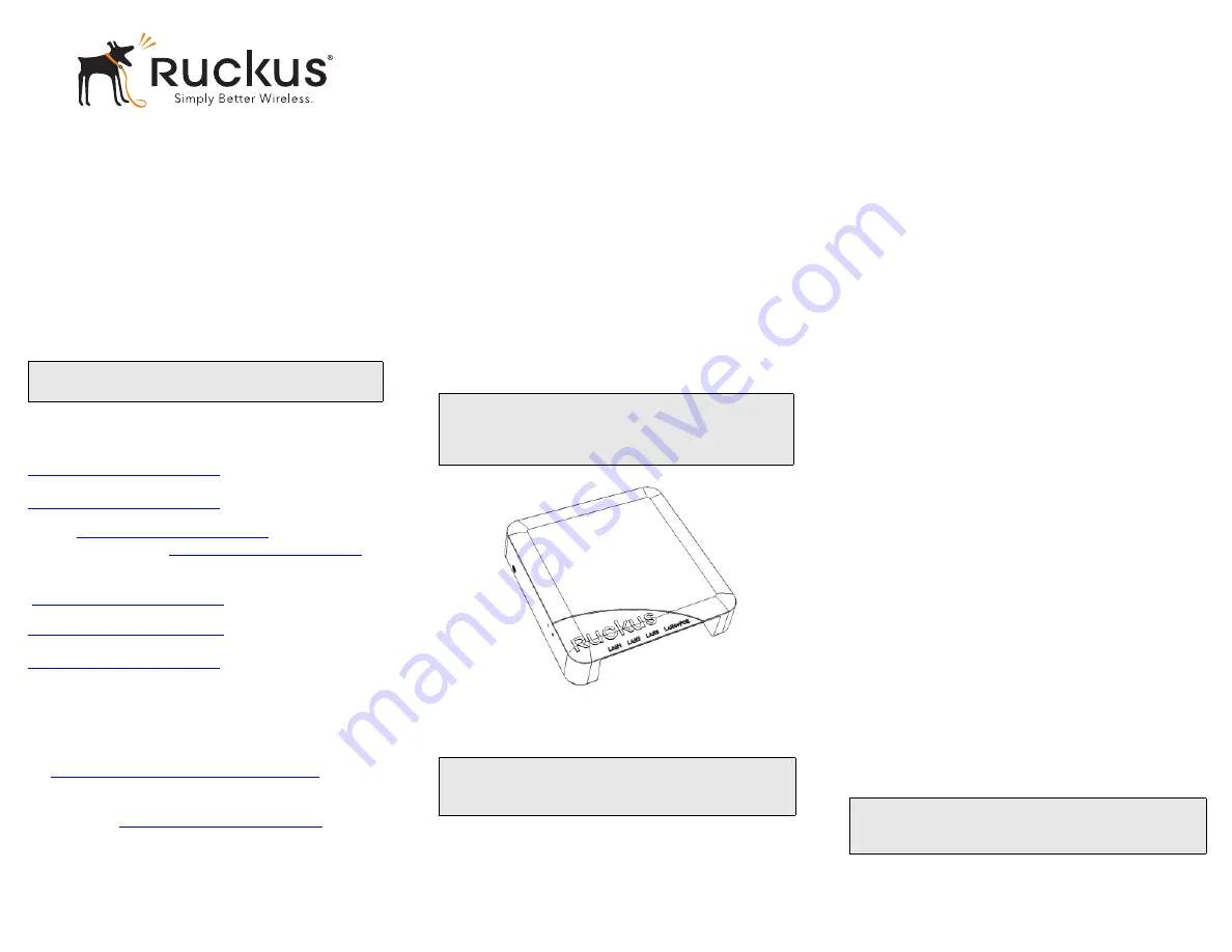
ZoneFlex 7055
Dual-Band Multimedia Wi-Fi
Wall Switch
Quick Setup Guide
This
Quick Setup Guide
provides step-by-step instructions
on how to set up your Ruckus Wireless ZoneFlex 7055
Multimedia Wi-Fi Wall Switch. After completing the steps
described in this Guide, you will be able to access the Wi-Fi
Wall Switch and begin providing wired and wireless network
access to users.
T
HIS
G
UIDE
IN
O
THER
L
ANGUAGES
请从以下网站获得该指南的简体中文版
https://support.ruckuswireless.com
.
請造訪以下網址,取得此手冊的繁體中文版本
https://support.ruckuswireless.com
.
Vous trouverez la version française de ce guide à l'adresse
suivante
https://support.ruckuswireless.com
.
こ の ガ イ ド の⽇本語版は
https://support.ruckuswireless.com
で ご覧 く だ さ い。
이
가이드의
한국어
버전은
웹
사이트
(
https://support.ruckuswireless.com
)
에서
확인하시기
바랍니다
.
Veja a versão em português (Brasil) deste guia em
https://support.ruckuswireless.com.
Puede ver la versión en español (América Latina) de esta guía en
https://support.ruckuswireless.com
B
EFORE
Y
OU
B
EGIN
Before deploying Ruckus Wireless products, please check for
the latest software and the release documentation.
•
Release Notes and User Guides are available at
http://support.ruckuswireless.com/documents
.
•
Software Upgrades, Open Source Information and Product
Warranty/Software License Agreement documents are also
available at:
http://support.ruckuswireless.com/
P
ACKAGE
C
ONTENTS
•
ZoneFlex 7055 Wi-Fi Wall Switch (Access Point)
•
Mounting bracket
•
(2) Low-profile Phillips head mounting screws
•
(2) Torx bracket screws
•
Regulatory flyer
•
This
Quick Setup Guide
S
ETUP
R
EQUIREMENTS
•
A Phillips screwdriver
•
A T10 Torx screwdriver
•
A notebook with an Ethernet port and a wireless card.
•
A standard US or EU-style wall outlet box, with an Ethernet
cable run through the wall from your LAN to the outlet box.
•
One of the following:
•
An IEEE 802.3af/at-compliant PoE switch.
•
An IEEE 802.3af/at-compliant PoE injector.
•
An optional DC power adapter (Ruckus part #902-
0170-XX10, sold separately)
\
S
TEP
1: P
REPARE
Y
OUR
C
OMPUTER
FOR
AP
S
ETUP
1
On your Windows 7 computer, open the
Network Con-
nections
(or
Network and Dial-up Connections
) control
panel:
Start > Control Panel > Network and Sharing Cen-
ter > Change Adapter Settings
2
When the
Network Connections
window appears, right-
click the icon for
Local Area Connection
, and then
select
Properties
.
When the Local Area Connection Properties dialog box
appears, select
Internet Protocol Version 4 (TCP/
IPv4)
from the scrolling list, and then click
Properties
.
The
TCP/IP Properties
dialog box appears.
3
Select
Use the following IP address
option (if it is not
already selected), and then make the following entries:
•
IP address
: 192.168.0.22 (or any address in the
192.168.0.x network--other than 192.168.0.1, which is
in use by the AP)
•
Subnet mask
: 255.255.255.0
•
Default gateway
: 192.168.0.1
Leave the DNS server fields empty.
4
Click
OK
to save your changes, and exit the
TCP/IP Prop-
erties
dialog box, and the
Local Area Connection Proper-
ties
dialog box. Your changes are put into effect
immediately.
S
TEP
2: C
ONNECT
THE
AP
TO
Y
OUR
C
OMPUTER
1
Remove the AP from its packaging and place it near your
computer.
2
Connect one end of an Ethernet cable to the
PoE In
LAN 5/Uplink
port on the rear of the AP, and connect
the other end to a PoE switch or the
Power Out
port on
the PoE injector.
•
If PoE power is not available, the AP can be powered
using an optional DC power adapter (Ruckus part
#902-0170-XX10, sold separately)
3
Using another Ethernet cable, connect one end to your
computer’s network port, and connect the other end to
another port on the PoE switch or to the
Data In/Net-
work
port on the PoE injector.
4
Provide power to the PoE injector/switch.
5
Verify that the
PWR
LED is steady green.
NOTE:
The ZoneFlex 7055 requires a minimum of Zone-
Flex firmware version 9.6 and above to operate.
WARNING!
DO NOT connect a PoE injector to any of the
four front ports, as this can seriously damage the device.
PoE in power supply should only be connected to the
PoE
In LAN/Uplink
port on the rear of the device.
NOTE:
The following instructions assume Windows 7 as the
operating system. Procedures for other OS’s are similar.
NOTE:
If PoE is not available, the 7055 can be powered
by Ruckus Wireless power adapter (part number 902-
0170-xx10).


