VC-450LR
Managed Industrial VDSL2 CO/CPE Modem.
USER’S MANUAL
Page 1: ...VC 450LR Managed Industrial VDSL2 CO CPE Modem USER S MANUAL...
Page 2: ...ability that may occur due to the use or application of the product s or circuit layout s described herein Maximum signal rate derived from IEEE Standard specifications Actual data throughput will var...
Page 3: ...uct near water for example in a wet basement or near a swimming pool Connect ONLY suitable accessories to the device Make sure to connect the cables to the correct ports DO NOT obstruct the device ven...
Page 4: ...CPE side by web config menu VC 450LR will allow operators worldwide to compete with cable andsatellite operators by offering services such as HDTV VOD videoconferencing high speed Internet access and...
Page 5: ...INT APPLICATION 11 CHAPTER 3 HARDWARE DESCRIPTION 14 3 1 FRONT PANEL 15 3 2 FRONT INDICATORS 15 3 3 REAR PANEL 18 3 4 SIDE PANEL 18 CHAPTER 4 CONFIGURE THE VC 450LR VIA WEB MANAGEMENT MENU 23 4 1 BASI...
Page 6: ...AN Line Statistics 41 4 4 4 LAN Statistics 42 4 4 5 ARP 43 4 5 XDSL SETUP 44 4 5 1 Master Slave mode profile Config 45 4 5 1 1 VDSL Config Overview 46 4 6 LAN SETUP 47 4 6 1 IPv4 Configuration 48 4 6...
Page 7: ...ticast MLD IPv6 62 4 8 8 SNMP 63 APPENDIX A CABLE REQUIREMENTS 66 APPENDIX B PRODUCT SPECIFICATION 69 APPENDIX C TROUBLESHOOTING 72 APPENDIX E COMPLIANCE INFORMATION 81 Warranty 84 Chapter 1 Unpacking...
Page 8: ...uding the original packing materials Use them to repack the unit in case there is a need to return for repair 2 If the product has any issue please contact your local distributor 3 Please use the prov...
Page 9: ...ide the right operating environment including power requirements sufficient physical space and proximity to other network devices that are to be connected Verify the following installation requirement...
Page 10: ...bling may be use between the MUX or HUB and an end node VDSL2 Port interface RJ 11 Terminal block combo All network connections to the RJ 11 terminal block sharing port must use 24 26 gauge with singl...
Page 11: ...oid scratches of metal housing Take out the 2pin 6pin terminal block from inside the accessory kit and install to the modem properly Figure 2 4 1 Please refer to install the DIN RAIL as following step...
Page 12: ...port has 2 connectors RJ 45 and terminal block It is used to connect from VC 450 CO using single pair phone cable to VC 450 CPE bridge side point to point solution Take note that VC 450 line port can...
Page 13: ...J 45 port This may damage the bridge Instead use only twisted pair cables with RJ 45 connectors that conform to Ethernet standard Notes 1 Be sure each twisted pair cable RJ 45 Ethernet cable does not...
Page 14: ...UAL Ver B 3 2 6 Point to Point Application First a quick overview on a complete setup of LAN extender Master Slave LAN extender VC 450LR is a LAN extender leverages the extraordinary bandwidth promise...
Page 15: ...VC 450LR Managed Industrial VDSL2 CO CPE Modem USER S MANUAL Ver B 3 Figure 2 6 VC 450LR Point to Point application 14...
Page 16: ...VC 450LR Managed Industrial VDSL2 CO CPE Modem USER S MANUAL Ver B 3 Figure 2 6 VC 450LR industrial grade application 15...
Page 17: ...re representation of a cable network with or without noise injection and crosstalk simulations 2 6 2 Connect the VC 450LR Master and the VC 450LR Slave to LAN Devices In the setup usually an Ethernet...
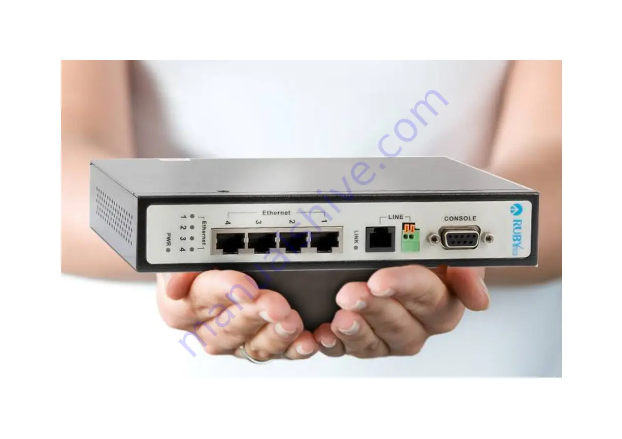
Page 18: ...dustrial VDSL2 CO CPE Modem USER S MANUAL Ver B 3 Chapter 3 Hardware Description This section describes the important parts of the VC 450LR It features the front panel and rear panel VC 450LR Outward...
Page 19: ...as Seven LED indicators The following Table shows the description Table 3 1 Table 3 1 LED Indicators Description and Operation LED Color Status Descriptions PWR Power LED Green On Steady Lights to ind...
Page 20: ...is sending or receiving data Off The Internet or network connection is down CO Green On Steady VC 450LR config on Master mode Off VC 450LR config on Slave mode Note It is normal for the connection be...
Page 21: ...VC 450LR Press over 5 seconds Load the default settings Power DC Jack External switching Power Adapter Input AC 85 240Volts 50 60Hz Output DC 12V 1A Line RJ 11 For connecting to a Master Slave device...
Page 22: ...side Figure 3 4 Figure 3 4 Rear connectors The following description introduce Dual power and Relay Contact Wiring the dual Power Inputs The VC 450LR has two sets of power inputs power 1 and power 2 w...
Page 23: ...Protection function automatically DC power will not be able to directly through the machine 2 Please note that if the DC power current exceeds 3A VC 450LR will enable Overload Current Protection func...
Page 24: ...Item Default Polarity Power Input1 Output State1 Power Input2 Output State2 Power Input1 Output State1 Power Input2 Output State2 Power Input1 Output State1 Power Input2 Output State2 Power 1 12V Mal...
Page 25: ...lay contacts of the 3 pins terminal block connector are used to detect a power failure warning event Wires connected to Warning Device over normal open contact COM NO for detecting power system If pow...
Page 26: ...for power and devices If power wiring and device wiring paths must cross make sure the wires are perpendicular at the intersection point Note Do not run signal or communications wiring and power wirin...
Page 27: ...iewed using Chrome or Firefox browsers In order to use the web browser to configure the device you may need to allow Web browser pop up windows from your device Web pop up blocking is enabled by defau...
Page 28: ...S MANUAL Ver B 3 4 1 BASIC Setup 4 1 1 Login Webpage The default username and password are admin Figure 4 1 1 Login Webpage 4 1 2 Display status When the device is running the status page will display...
Page 29: ...odem USER S MANUAL Ver B 3 MAC Address and System Up Time as shown in Figure 4 1 2 Figure 4 1 2 Device Info 4 2 Select the Menu Level There is an easy Setup for end users at the setup of VC 450LR with...
Page 30: ...al VDSL2 CO CPE Modem USER S MANUAL Ver B 3 Home Logout for more detail con gura ons Figure 4 2 Select the Menu Level 4 3 System Select System The menu below will be used frequently It includes the su...
Page 31: ...nagemant Log level Logs Service Control CWMP Internet Time Reboot Restore Default A screen is displayed as shown in Figure 4 3 Figure 4 3 System 4 3 1 Configuration Backup To backup the con gura on se...
Page 32: ...Modem USER S MANUAL Ver B 3 Figure 4 3 1 Configuration Backup 4 3 2 Configuration Restore To restore your con gura on se ng value click on the Con gura on Restore link in the le naviga on bar A screen...
Page 33: ...ns the following detail Click Browse to select a specific file name in preparation for modem settings Click Update Settings to start updating 4 3 3 Update Software To update so ware click on the Updat...
Page 34: ...3 Update Software Note The update process takes about 12 minutes to complete and your Broadband Modem will reboot 4 3 4 Account Management To change or create passwords click on the Account Management...
Page 35: ...m USER S MANUAL Ver B 3 Figure 4 3 4 Account Management Password 4 3 5 Log Level Click on the Log level link in the le naviga on bar on the right page you will see how to enable Log or Log Server A sc...
Page 36: ...Account Management Log Level 4 3 6 Service Control Click on Service Control link in the le naviga on bar on the right page you will see how to enable ACL Click add to con g Protocol IP Protocol Type E...
Page 37: ...VC 450LR Managed Industrial VDSL2 CO CPE Modem USER S MANUAL Ver B 3 36...
Page 38: ...igure 4 3 6 Service Control IP Address Configuration 4 3 7 CWNP TR 069 Settings Click on CWMP link in the left navigation bar to create TR 069 connection and setup ACS URL ACS User Name ACS Password a...
Page 39: ...MANUAL Ver B 3 Figure 4 3 7 TR069 Settings 4 3 8 Internet Time If SNTP server could not be connected to allow the device to synchronize the system clock to the global Internet Please setup Internet T...
Page 40: ...er B 3 Figure 4 3 8 NTP Settings 4 3 9 Restore Default Se ng to the factory defaults click on the Restore Default link in the le naviga on bar and press Restore Default Se ngs the device will reboot i...
Page 41: ...Modem USER S MANUAL Ver B 3 Figure 4 3 9 Restore Default Settings 4 4 Status Setup Select Status It includes the sub menus of Device Infoma on LAN Network Ethernet WAN Sta s cs LAN Sta s cs ARP A scre...
Page 42: ...Modem USER S MANUAL Ver B 3 Figure 4 4 Device informations 4 4 1 LAN Network Click on the LAN Network link in the le naviga on bar you will see the status of IPv4 IPv6 Address for this device A screen...
Page 43: ...ANUAL Ver B 3 Figure 4 4 1 LAN Network information 4 4 2 Ethernet Click on the Ethernet link in the le naviga on bar you will see the Ethernet Status Speed and Duplex of LAN1 LAN2 LAN3 LAN4 for this d...
Page 44: ...S MANUAL Ver B 3 Figure 4 4 2 LAN Ethernet information 4 4 3 WAN Line Statistics Click on the WAN Sta s cs link in the le naviga on bar you will see the Received and Transmi ed status for this device...
Page 45: ...dem USER S MANUAL Ver B 3 Figure 4 4 3 Statistics WAN Line 4 4 4 LAN Statistics Click on the LAN Sta s cs link in the le naviga on bar you will see the Received and Transmi ed status for LAN1 4 A scre...
Page 46: ...USER S MANUAL Ver B 3 Figure 4 4 4 Statistics LAN 4 4 5 ARP Click on the ARP link in the le naviga on bar you will see the records of Flags HW Address and Device status for di erent IP addresses A sc...
Page 47: ...AL Ver B 3 Figure 4 4 5 ARP setting 4 5 xDSL Setup Select xDSL It includes the sub menus of Dsl Status Dsl Con g Click on the Dsl Status link in the le naviga on bar you will see VDSL Informa on for t...
Page 48: ...B 3 Figure 4 5 VDSL Information 4 5 1 Master Slave mode profile Config Click on the Dsl Con g link in the le naviga on bar there are 9 VDSL modes selectable the default se ng is 3 Master Mode Sy Auto...
Page 49: ...VC 450LR Managed Industrial VDSL2 CO CPE Modem USER S MANUAL Ver B 3 Figure 4 5 1 VDSL Setup 4 5 1 1 VDSL Config Overview Below table clarify the se ngs of 9 di erent VDSL modes NO Config Note 48...
Page 50: ...le re transmition SNRM 12 6 NSy Auto G INP_17 2 41 SNRM 12 12 non symmetric Auto enable G INP enable re transmition SNRM 12 7 Sy 30a D2 2M G INP_17 2 41 Rate 20 20 SNRM 24 24 Symmetric 30a disable 0 2...
Page 51: ...S MANUAL Ver B 3 Figure 4 6 LAN 4 6 1 IPv4 Configuration Click on the IPv4 Con gura on link in the le naviga on bar Click Apply at any me during con gura on to save the informa on that you have entere...
Page 52: ...Ver B 3 Figure 4 6 1 IPv4 Configuration 4 6 2 IPv6 Configuration Click on the IPv6 Con gura on link in the le naviga on bar Click Apply at any me during con gura on to save the informa on that you ha...
Page 53: ...E Modem USER S MANUAL Ver B 3 Figure 4 6 2 IPv6 Configuration 4 6 3 IPv6Static Route Click on the IPv6Sta c Route link in the le naviga on bar Click add to a new page and setup Sta c Route A screen is...
Page 54: ...VC 450LR Managed Industrial VDSL2 CO CPE Modem USER S MANUAL Ver B 3 Figure 4 6 3 IPv6Static Route 53...
Page 55: ...2 CO CPE Modem USER S MANUAL Ver B 3 4 6 4 Ethernet Mode Click on the Ethernet Mode link in the le naviga on bar Choose the speed Auto 10Mb s 100Mb s of LAN1 4 and click Apply to setup Figure 4 6 4 LA...
Page 56: ...LR Managed Industrial VDSL2 CO CPE Modem USER S MANUAL Ver B 3 4 7 Qos Setup Select Qos It includes the sub menus of Qos Queue Qos Classi ca on A screen is displayed as shown in Figure 4 7 Figure 4 7...
Page 57: ...USER S MANUAL Ver B 3 4 7 1 Qos Queue Click on Qos Queue link in the le naviga on bar on the right page you will see how to enable Qos and Upstream Queue Se ngs There are four modes of Qos pro les A s...
Page 58: ...VC 450LR Managed Industrial VDSL2 CO CPE Modem USER S MANUAL Ver B 3 Figure 4 7 1 Qos Global Settings 4 8 Applications 57...
Page 59: ...lnet Service SSH Service Printer Share Mul media Share UPnP Mul cast IGMP Mul cast MLD SNMP A screen is displayed as shown in Figure 4 8 Figure 4 8 Applications 4 8 1 Telnet Service Setup for Security...
Page 60: ...n is displayed as shown in Figure 4 8 1 Figure 4 8 1 Service Telnet Service Setup 4 8 2 SSH Service Telnet Encryption Click on SSH Service link in the le naviga on bar on the right page you will see h...
Page 61: ...S MANUAL Ver B 3 Figure 4 8 2 SSH Service Setup 4 8 3 Printer Sharing Click on Printer Share link in the le naviga on bar on the right page you will see how to enable Printer Service and type Queue Na...
Page 62: ...MANUAL Ver B 3 Figure 4 8 3 Printer Service Setup 4 8 4 Multimedia Sharing Click on Mul media Share link in the le naviga on bar on the right page you will see how to enable DMS and select Share Fold...
Page 63: ...PE Modem USER S MANUAL Ver B 3 Figure 4 8 4 Multimedia Share Setup 4 8 5 UPnP Click on UPnP link in the le naviga on bar on the right page you will see how to enable UPnP and add Blacklist A screen is...
Page 64: ...dem USER S MANUAL Ver B 3 Figure 4 8 5 UPnP 4 8 6 Multicast IGMP Click on Mul cast IGMP link in the le naviga on bar According to the se ng if you want to test IGMP func on you only need to enable IGM...
Page 65: ...SER S MANUAL Ver B 3 Figure 4 8 6 IGMP Settings 4 8 7 Multicast MLD IPv6 Click on Mul cast MLD link in the le naviga on bar According to the se ng if you want to test MLD func on you only need to enab...
Page 66: ...dustrial VDSL2 CO CPE Modem USER S MANUAL Ver B 3 Figure 4 8 7 MLD Settings 4 8 8 SNMP Click on SNMP link in the le naviga on bar on the right page you will see how to enable SNMP func on VC 450LR sup...
Page 67: ...450LR Managed Industrial VDSL2 CO CPE Modem USER S MANUAL Ver B 3 Figure 4 8 8 SNMP Settings Download MG SOFT MIB Browser Below picture indicate how to use the so ware and connect remote SNMP agent 6...
Page 68: ...VC 450LR Managed Industrial VDSL2 CO CPE Modem USER S MANUAL Ver B 3 Select OID 1 3 6 1 2 1 1 3 SysUp Time 67...
Page 69: ...dustrial VDSL2 CO CPE Modem USER S MANUAL Ver B 3 Appendix A Cable Requirements A 1 Ethernet Cable A CAT 3 7 UTP unshielded twisted pair cable is typically used to connect the Ethernet device to the M...
Page 70: ...Table A 1 Table A 1 RJ 45 Ethernet Connector Pin Assignments PIN MDI MDI X Figure A 1 Standard RJ 45 repectacle connector Signal Media Dependant interface Signal Media Dependant interface cross 1 TX...
Page 71: ...LR Managed Industrial VDSL2 CO CPE Modem USER S MANUAL Ver B 3 Figure A 2 Pin Assignments and Wiring for an RJ 45 Straight Through Cable Figure A 3 Pin Assignments and Wiring for an RJ 45 Crossover Ca...
Page 72: ...d it consists of six pins POTS plain old telephone services use pins 3 and 4 for voice transmission A telephone cable is shown below Figure A 4 A B Figure A 4 Telephone cable The A and B connectors on...
Page 73: ...rts SNMP V1 V2 Supports RJ11 Terminal Block combo port Supports Master Slave Mode selectable by Web config Supports Jumbo frame up to 2k Supports up to VDSL2 profile 30a Supports G 998 4 G INP Support...
Page 74: ...J 45 10 100Mbps 1x RJ 11 Line port 1x Terminal Block LED Indicators 1 x Power LED 4 x Link Active Status for Ethernet port 1 x Link LED for VDSL2 port 1 x CO Master LED Switch method Store and forward...
Page 75: ...em USER S MANUAL Ver B 3 Fanless free air cooling Storage Temperature 40 C 70 C 40 F 158 F Humidity 5 95 non condensing Dimensions 182x142x35 5 mm 7 16 x5 59 x1 39 Weight About 0 8 kg EMC Certificatio...
Page 76: ...er cord If these measures fail to resolve the problem have the unit power supply replaced by a qualified distributor Note Please refer to power status table to check power input status Section 3 3 2 S...
Page 77: ...length or link time over 3 minutes 3 4 Or try to change band profile as 17a for getting long reach Note Phone wire must meet CAT 3 standard or above and twisted pair otherwise will cause more cross ta...
Page 78: ...gate data rates up to 200 Mbit s downstream and upstream on twisted pairs using a bandwidth up to 30 MHz VDSL2 deteriorates quickly from a theoretical maximum of 250 Mbit s at source to 100 Mbit s at...
Page 79: ...Smartbit we recommend test that by IPERF program and TCP window size must be settled max 64k the parameter as iperf c server IP address i 1 t 50 w 65535 for client side 6 Question I just bought a VC 4...
Page 80: ...segment Regarding how to configure a default gateway at switch bridged mode for crossing various network segments Configuration gateway example from static routing Destination LAN IP 0 0 0 0 Subnet Ma...
Page 81: ...button and the modem will go through its reboot process The default ip is 192 168 16 249 When logging in the default username and password both are admin 9 Question What is the maximum Ethernet frame...
Page 82: ...n alternate environment where you are sure that all the other components are functioning properly Transmission Mode The default method of selecting the transmission mode for RJ 45 ports is 10 100 Mbps...
Page 83: ...integrity with a power on reset Turn the power to the switch off and then on several times If the problem still persists and you have completed all the preceding diagnoses then contact your dealer App...
Page 84: ...technician for help Changes or modifications not expressly approved by the party responsible for compliance could void the user s authority to operate the equipment If this telephone equipment causes...
Page 85: ...ipment can generate use and radiate radio frequency energy and if not installed and used in accordance with the instruction manual may cause harmful interference to radio communications Operation of t...
Page 86: ...pliance now being required for CE marking of products RoHS 2 also added Categories 8 and 9 and has additional compliance recordkeeping requirements Directive 2015 863 was published in 2015 by the EU w...
Page 87: ...rs made or performed by any person not under control of the original owner The above warranty is in lieu of any other warranty whether express implied or statutory including but not limited to any war...