background image

60  Firmware Download

KP32CLD

Bosch Security Systems, Inc.

User Manual

 F.01U.193.294

Rev. 10

NOTE:

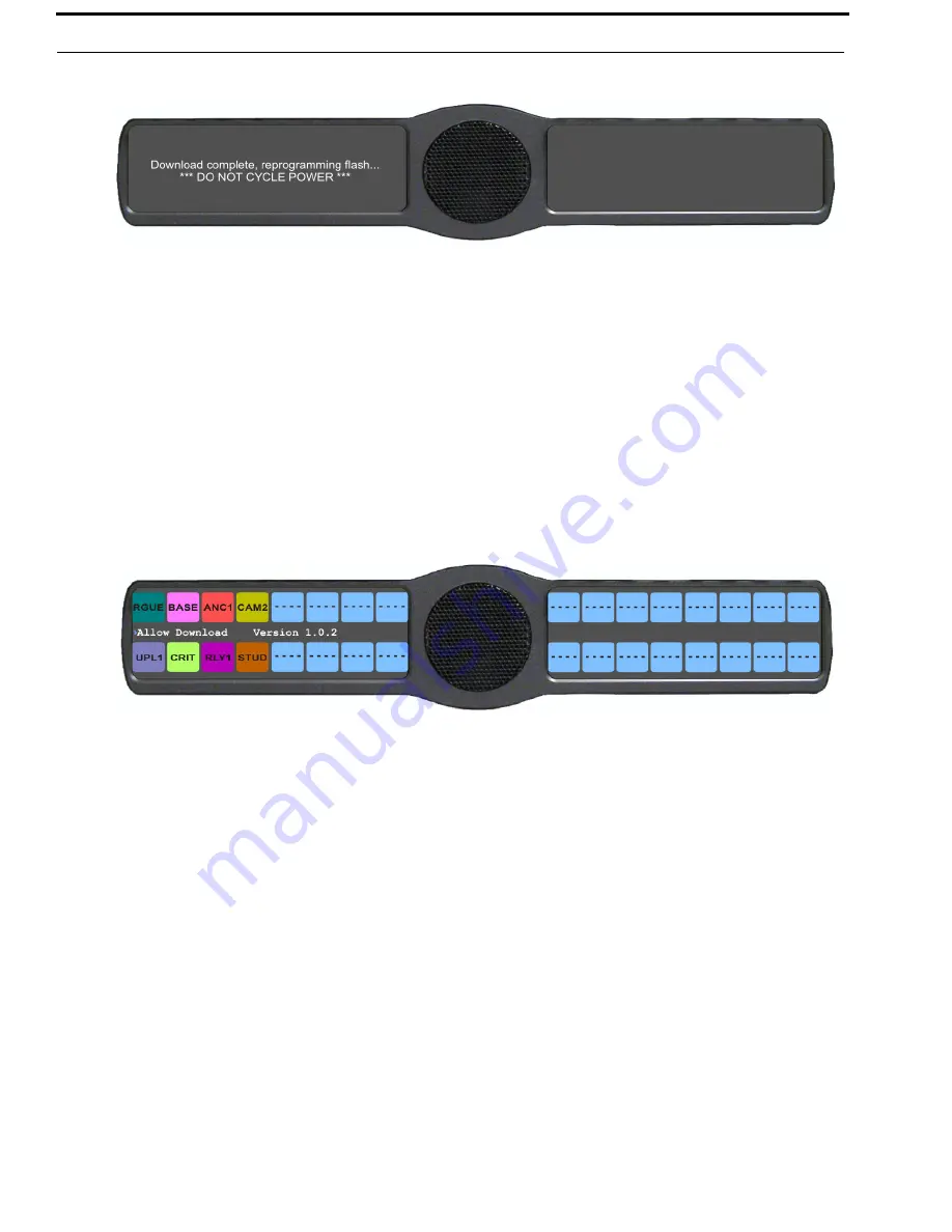
Once the Boot Loader is finished downloading, it reboots itself. 

Enable The Boot Loader On The Keypanel (v 1.1.0 and later)

By enabling the boot loader on the keypanel, updating the firmware on the keypanel is simple. Once you have enabled the 
keypanel to allow the firmware to be downloaded to it, you can use AZedit to do the rest of the work.

To

 enable the boot loader on the keypanel

, do the following:

1.

While pressing the 

Main Vol 

and 

Aux Vol

 encoders at the same time, press the 

MENU

 button.

The main menu appears.

2.

Using the 3(

) or 6(

), select 

Service

.

3.

Press the 

SEL

 button.

The Service menu options appear.

4.

Using the 3(

) or 6(

), select 

Boot Code

.

5.

Press the 

SEL

 button.

Allow Download and Version X.X.X (where X represents the version numbers)

.

NOTE:

If the firmware version is older than version 1.0.2 question marks (?) appear in the display window.

6.

Using the 3(

) or 6(

), select 

Allow Download

.

7.

Press the 

SEL

 button.

The CLD family keypanel allows firmware downloads

.

NOTE:

If the keypanel is powered off or loses power, the state of the Allow Download option resets to not enabled. 

You must reconfigure the option for it to allow downloads.

Summary of Contents for DKP 16 CLD

Page 1: ...F 01U 193 294 Rev 10 JANUARY 2012 CLD Color Keypanel Family User Manual up to and including version 1 3 1 KP 32 CLD DKP 16 CLD EKP 32 CLD ...

Page 2: ... php DISCLAIMER The manufacturer of the equipment described herein makes no expressed or implied warranty with respect to anything contained in this manual and shall not be held liable for any implied warranties of fitness for a particular application or for any indirect special or consequential damages The information contained herein is subject to change without prior notice and shall not be con...

Page 3: ...f the provided plug does not fit into your outlet consult an electrician for replacement of the obsolete outlet 10 Protect the power cord from being walked on or pinched particularly at plugs convenience receptacles and the point where they exit from the apparatus 11 Only use attachments accessories specified by the manufacturer 12 Use only with the cart stand tripod bracket or table specified by ...

Page 4: ...Bosch Security Systems Inc User Manual F 01U 193 294 Rev 10 4 KP32CLD ...

Page 5: ... Optional RVON 2 CLD Module 12 Connector Pinouts 13 Accessing the Switch Bank 16 INSTALLATION 19 Requirements 19 KP 32 CLD Installation 20 Power Up 20 Address Setting 21 General Information 21 Connections 22 Frame Connector 22 Headset Connector 22 Panel Microphone Connector 22 Footswitch Connector 22 BASIC OPERATION 23 Intercom Keys and Displays 23 Color Display Descriptions for Intercom Keys 23 D...

Page 6: ...41 Mic Select 42 User Programmable Keys 44 Keypanel Color Window 45 Function Types Page 46 Select Intercom Drop Down Menu 46 Apply Button 46 Clear Button 46 Function Type Column 47 Color Column 47 Show Default Colors Check Box 47 Key Assignment Page 48 Select Function Type Drop Down Menu 48 Apply Button 49 Clear Button 49 Function Number Column 50 Color Column 50 Show Default Colors Check Box 50 A...

Page 7: ...tions Menu Panel Mic 89 Audio Options Menu Preamp Out 90 Audio Options Menu Sidetone 90 Audio Options Menu Speaker 92 Audio Options Menu Tone Gen 93 Menu System Display 95 Display Menu Assign Type 96 Display Menu Auto Dial 97 Display Menu Chans On 97 Display Menu Chime 98 Display Menu Exclusive 98 Display Menu Key Groups 99 Display Menu Key List 99 Display Menu LCP 16 CLD 100 Display Menu Level 2 ...

Page 8: ...Menu Alphas 127 Service Menu Aux Mtx Inputs 128 Service Menu Baud Rate 129 Service Menu Display Dim 130 Service Menu Footswitch 131 Service Menu Key View 132 Service Menu Keypad 133 Keypad Sequence 133 Backlight 134 Service Menu Local GPIO 134 Service Menu Reset Cfg 137 Service Menu RVON Setup 137 Service Menu Scr Saver 140 Service Menu Set Address 142 Service Menu Snoop Tally 143 Service Menu Tes...

Page 9: ...N 2 Card 188 KP 32 CLD 188 DKP 16 CLD 191 Addresses and the RVON 2 195 Configure the RVON 2 from the KP CLD 195 Set the IP Address from the Service Level Menu 195 Menu System RVON Offers Only available with the RVON 2 option card installed 197 RVON 2 Option Card Matrix Connection 197 RVON 2 Option Card Matrix Port Configuration 197 RVON 2 Option Card Aux Port Configuration 198 Configure a RVON car...

Page 10: ...Bosch Security Systems Inc User Manual 6 KP32CLD Rev 10 F 01U 193 294 CYRILLIC SUPPORT 219 AZedit and Cyrillic Support 219 ...

Page 11: ...y Icons 39 FIGURE 16 Keypanel Colors Window 43 FIGURE 17 Function Type and Color Columns 45 FIGURE 18 Key Assignments Page 46 FIGURE 19 Function Number and Color Columns 47 FIGURE 20 Assignments Groups Page 48 FIGURE 21 Miscellaneous Colors Page 50 FIGURE 22 Main Audio Options Menu 63 FIGURE 23 Frequency Response Preset 1 20Hz to 300Hz 65 FIGURE 24 Frequency Response Preset 2 300Hz to 900Hz 65 FIG...

Page 12: ...el 142 FIGURE 41 EKP CLD Expansion Panel Reference View Front and Rear 180 FIGURE 42 Expansion Panel Cabling 181 FIGURE 43 RVON Offers Top Level Menu Option 195 FIGURE 44 Booting up in Kanji 205 FIGURE 45 LCP 16 CLD Menu Structure on the KP 32 CLD 213 FIGURE 46 LCP 16 CLD Front Panel 214 FIGURE 47 Hardware Setup for a KP 32 CLD and 2 LCP 16 CLD 214 ...

Page 13: ...anel is ergonomically designed to fit easily into any control room or truck application The back panel is optimized for future expansion Multi Directional Keys 32 multi directional keys used for talk listen and emulation of traditional level control functions Future Expansion Designed to allow for an expansion panel and optional connections to the matrix through current and future standard transmi...

Page 14: ...n page 12 for pinouts Expansion RJ 45 see RJ 45 EXP expansion on page 13 for pinouts GPIO MIC OUT Male XLR 3 see XLR 3 male Mic OUT on page 12 for pinouts GPIO MIC IN Female XLR 3 see XLR 3 female Mic IN on page 12 for pinouts GPIO Aux 1 2 Female XLR 3 see XLR 3 female AUX 1 2 on page 12 for pinouts GPIO Aux 3 6 DB 15 see DB 15 male Aux 3 Aux 4 Aux 5 Aux 6 on page 11 for pinouts GPIO Headset DB 9 ...

Page 15: ...KP32CLD Introduction 5 Bosch Security Systems Inc User Manual F 01U 193 294 Rev 10 KP 32 CLD Block Diagram FIGURE 1 KP 32 CLD Block Diagram ...

Page 16: ...e is dependent upon the Audio Out configuration see Audio Options Menu Speaker on page 90 7 CLR CWW Key Clears the panel menu or answers the call waiting window 8 Menu button For detailed explanation see KP 32 CLD Menu System on page 61 9 FWD button Allows you to go forward in the menu structure 10 BACK button Allows you to go backward in the menu structure 11 UPG 1 button Assigns any function fro...

Page 17: ...r LCP for future expansion 6 Boot Loader Reset For more information see Download Firmware Using the BLR Function on page 57 7 DB 9 male Connector Footswitch Speaker 8 XLR 3 female Connector Aux 1 9 XLR 3 female Connector Aux 2 10 XLR 3 female Connector Mic IN 11 XLR 3 male Connector Mic OUT Optional RVON 2 CLD Module 12 Ethernet RJ 45 connector RVON 2 Matrix Connection FIGURE 3 KP 32 CLD Back Pane...

Page 18: ...on page 61 6 FWD button Allows you to go forward in the menu structure 7 BACK button Allows you to go backward in the menu structure 8 UPG 1 button User can assign any function from the menu structure to this key 9 UPG 2 button User can assign any function from the menu structure to this key 10 CLR CWW Key Clears the panel menu or answers the call waiting window 11 Aux Volume The Aux volume adjust...

Page 19: ...connector Can be used to charge a cell phone or download upload data to or from the keypanel 2 4 5 pin XLR female Headset 6 7 pin XLR female Headset and Footswitch connection 3 4 5 pin XLR female Headset 6 7 pin XLR female Headset and Footswitch connection FIGURE 5 DKP 16 CLD Front Right and Left Side Views ...

Page 20: ...Connector Frame 4 RJ 45 Connector Frame Optional GPI 32 CLD Connector Module 5 XLR 3 female Connector Aux 1 6 XLR 3 female Connector Aux 2 7 DB 9 male Connector Aux 3 Footswitch and Speaker 8 DB 9 male Connector Opto 1 3 IN 9 XLR 3 male Connector Mic OUT 10 XLR 3 female Connector Mic IN 11 DB 9 male Connector Relay 1 2 3 Optional RVON 2 CLD Module 12 Ethernet RJ 45 connector RVON 2 Matrix Connecti...

Page 21: ...GND FS Pin 7 Footswitch DB 15 male Aux 3 Aux 4 Aux 5 Aux 6 Pin Assignment 1 AUX 3 Input 2 AUX 3 Input 3 AGND 4 AUX 4 Input 5 AUX 4 Input 6 AGND 7 DGND 8 5VD 9 AGND 10 AUX 5 Input 11 AUX 5 Input 12 AUX 6 Input 13 AUX 6 Input 14 DGND 15 5VD DB 9 Relay 1 2 3 4 RLY 1 RLY2 RLY3 Common Pin 2 Pin 5 Pin 8 NC Pin 1 Pin 4 Pin 7 NO Pin 3 Pin 6 Pin 9 DB 9 male Opto Isolator 1 4 Pin Assignment 1 GND 2 GND 3 GN...

Page 22: ...ch 6 Speaker Left 7 NC 8 Speaker Right 9 AGND XLR 3 female AUX 1 2 Pin Assignment 1 GND 2 Input 3 Input XLR 3 female Mic IN Pin Assignment 1 AGND 2 Audio and DC Bias 3 AGND XLR 3 male Mic OUT Pin Assignment 1 AGND 2 Audio Output 3 Audio Output DB 9 male Frame Pin Assignment 1 RS485 2 RS485 3 Audio IN from Matrix shield 4 Audio OUT to Matrix 5 Audio OUT to Matrix 6 Data Shield 7 Audio IN from Matri...

Page 23: ...2 GND 3 GND 4 GND 5 RS485 6 RS485 7 GND 8 Reserved RJ 45 LCP Pin Assignment 1 Data to LCP 2 Clock OUT 3 Data from LCP 4 GND 5 GND 6 GND 7 GND 8 GND DB 9 male Opto Isolator 1 2 DKP 16 Only Pin Assignment 1 5 V digital current limiting resistor 1K 2 5 V digital current limiting resistor 1K 3 DGND 4 DGND 5 DGND 6 Switch Contact Input 1 7 Switch Contact Input 2 8 Switch Contact Input 3 9 NC DB 9 male ...

Page 24: ...osch Security Systems Inc User Manual F 01U 193 294 Rev 10 Accessing the Switch Bank To access the switch bank do the following 1 Remove the four 4 screws on the top of the unit 2 In no certain order remove the following screws ...

Page 25: ... Rev 10 3 Carefully lift the chassis up and back to remove the back panel Note the back panel is still attached by the DB 9 frame ribbon cable 4 Using a pen or screwdriver set the switches to the type of operation you desire For operation modes see Figure 7 Figure 8 or Figure 9 ...

Page 26: ...ch 3 ON Switch 4 OFF FIGURE 7 RTS Standard Cable USOC Switch 1 ON Switch 2 OFF Switch 3 ON Switch 4 OFF FIGURE 8 Standard CAT 5 Cable using pin 1 and pin 2 for RS485 functionality 568A Switch 1 OFF Switch 2 ON Switch 3 OFF Switch 4 ON FIGURE 9 Standard CAT 5 Cable using pin 7 and pin 8 for RS485 functionality 568B ...

Page 27: ...Installation Requirements The following keypanel firmware versions are needed for the specified KP CLD model KP CLD version 1 0 1 KP CLD with GPIO option card version 1 0 1 KP CLD with RVON 2 option card version 1 0 2 NOTE You must be running RVON firmware 2 1 6 or later ...

Page 28: ...ur keypanel for operation Power Up Connect a power cord to the unit and then to an AC power source The power supply accepts 100 240 VAC 50 60 Hz At power up if the keypanel is connected to the matrix the alphanumeric display shows dashes in the light blue color key After several seconds to a minute the intercom key assignments display with the appropriate color keys and alphas NOTE If the keypanel...

Page 29: ...p www rtsintercoms com manuals php Cronus see Cronus user manual P N 9350 7770 000 which can be found at http www rtsintercoms com manuals php Zeus III see the Zeus III user manual P N 9350 7843 000 which can be found at http www rtsintercoms com manuals php Zeus III LE LE see the Zeus III LE LE user manual P N 9350 7843 500 which can be found at http www rtsintercoms com manuals php NOTE If you a...

Page 30: ... of the front rear panel speaker and a separate microphone Headphones may be connected for use with a separate microphone Panel Microphone Connector A panel microphone may be connected to the front or rear with optional GPI 32 CLD option card installed of the unit for talking with either the front rear panel speaker or headphones used for listening The connector accepts MCP5 MCP6 or MCP90 series p...

Page 31: ...fault Key Colors to help you determine the available key assignment colors TABLE 2 Default Key Colors Default Color Description Amber Waiting for Footswitch Bright Green Listen Indicator Local Matrix Brown IFB Special List Teal Point to Point Dark Yellow ISO Light Blue Unassigned Test Mode with Talk and Listen Indicators Pale Yellow Special Functions Magenta Relay Pink Party Line Red Remote Matrix...

Page 32: ...n see Download Firmware to the Color Keypanel Family From AZedit on page 53 Footswitch Active The footswitch is active Footswitch Enabled The footswitch is enabled but not active NOTE When a keypanel key is pressed while the Footswitch is enabled the key display turns amber to signify that it is waiting for footswitch Front Headphones The front headphones are enabled Front Headset The front headse...

Page 33: ...ctive mic but does not flash Rear Speaker The rear speaker is active To activate the rear speaker see Audio Options Menu Speaker on page 90 Rear Speaker Muted The rear speaker is muted To mute the rear speaker see Mute the Microphone Speaker on page 39 Both Headphones Both front and rear headphones are enabled To enable the front headphones see Audio Options Menu Headset Spkr on page 78 Both Heads...

Page 34: ...nu Tone Gen on page 91 Main Volume Bar The main volume bar is used to control the volume for the speaker rear speaker headset and rear headset If the volume of a speaker or headset is turned down to mute the non flashing mute icon appears on the speaker or headset NOTE If both the front and rear speaker or headset are enabled the mute icon only appears if both the front and rear volumes are in the...

Page 35: ...Reference To select the desired keypad sequence do the following 1 On the KP 32 CLD press the MENU button The top level menu appears 2 Using the 3 or 6 scroll to Service 3 Press the SEL button The Service menu appears 4 Using the 3 or 6 scroll to Keypad 5 Press the SEL button Sequences and Backlight appear in the display window 6 Verify Sequences is highlighted 7 Press the SEL button Classic and D...

Page 36: ...he menu option highlighted For example if Display is highlighted in the display window and FWD is pressed the second level of the display menu appears BACK button The BACK button moves you backward one level through the menu structure NOTE If you are at the top level of the menu structure and press BACK you cannot move backward any further UPG 1 button The UPG 1 button is used to assign a frequent...

Page 37: ...E button access the TIF connection allowing you to dial out from the keypanel 3 button The 3 button moves you forward through the menu structure or available key assignments one at a time When in the MENU mode pressing the 3 button moves you forward through the menu option highlighted 6 button The 6 button moves you backward through the menu structure or available key assignments one at a time Whe...

Page 38: ...plays a list of current callers to the keypanel Type Displays the assignment types of all the configured keypanel keys Mtx Displays the Matrix system of each key assignment Tone Opens the Tone Generator menu For more information see Audio Options Menu Tone Gen on page 91 VRst Opens the Key Volumes Reset menu For more information see Press the SEL button A blue arrow appears next to the selected op...

Page 39: ... Listen Indicator shown in Figure 12 displays a visual indicator when the talk and or listen key is active The talk and listen states of each key are represented by an LED like horizontal bar at the bottom talk and top listen of each key For the KP CLD family of keypanels you must be running CLD keypanel firmware version 1 1 1 to have talk and listen indicators supported on the display keys By def...

Page 40: ...Crosspoint The range for this feature is 80dB to 6dB and Mute NOTE A listen assignment must be configured for key gain to be enabled on a keypanel key To change key volumes do the following 1 On the KP 32 CLD front panel Press the keypanel key to the right to increase the listen gain for the selected key assignment Press the keypanel key to the left to decrease the listen gain for the selected key...

Page 41: ...he following On the KP 32 CLD turn the MAIN VOLUME encoder to the right to increase the volume for the listen destination OR Turn the MAIN VOLUME encoder to the left to decrease the volume for the listen destination NOTE When the MAIN VOLUME encoder is turned the volume level bar appears in the display window NOTE You can save the volume adjustments to be power up defaults using Service Menu Save ...

Page 42: ...do the following On the KP 32 CLD turn the AUX VOLUME encoder to the right to increase the volume for the listen source OR Turn the AUX VOLUME encoder to the left to decrease the volume for the listen source NOTE When the AUX VOLUME encoder is turned the volume level bar appears in the display window NOTE You can save the volume adjustments to be power up defaults using Menu System Save Config on ...

Page 43: ...sch Security Systems Inc User Manual F 01U 193 294 Rev 10 To change the focus of the volume control do the following On the KP 32 CLD push the AUX VOLUME encoder once The aux volume focus switches to next source shown if applicable ...

Page 44: ... talk assignment activating the key causes the crosspoint levels to diminish for any other intercom ports currently listening to the same destination and are in the same DIM tables Operation of Intercom Keys with Options Group Option Keys Activating the master key in a key group activates all keys in the group according to each key s individual key assignment Activating a slave key does not affect...

Page 45: ... the following NOTE If you are using the default keypad see Default Keypad Sequence on page 156 1 On the KP 32 CLD keypad press the 6 or 3 key to scroll through the list of point to point connections avail able The selected port is highlighted in white NOTE You can also use the 5 or 3 to page scroll through the list of ports available Page scroll is useful when you have a large intercom system and...

Page 46: ... CWW window do the following When the CWW window is populated tap up on the CWW key NOTE If a second call is received in the CWW while a caller name is already displayed the Call Waiting window flashes To answer a second call do the following Tap up to clear the first name and then hold the key down to talk to the second caller NOTE By default only the names of callers who are not currently assign...

Page 47: ...ical window above key 16 The CWW displays three 3 calls at a time only two 2 in Kanji with a scroll arrow appearing if there are more then three 3 calls in the list Firmware version 1 1 1 requires MCII e version 2 1 0 or later Graphical Call Waiting Window Operation Use Table 5 and Figure 13 to understand the different states of the CWW FIGURE 13 Graphical Call Waiting Window TABLE 5 Graphical CWW...

Page 48: ... Calls When a call is received at the KP CLD panel the graphical CWW list appears on the keypanel display Unlike the keypanel talley indicators in previous keypanel versions the graphical CWW list appears on the keypanel display Unlike the keypanel talley indicators in previous keypanel versions the graphical CWW and the call flashes tallies rather than the CWW button You can configure the tally d...

Page 49: ...s not visible press the CWW key to make it visible and the call selected 2 Press up on the CWW key once to remove the selected call 3 Repeat step 2 as necessary Mute the Microphone Speaker Depending on the source selected shown in the display window when the Mic Mute switch is pressed UP the corresponding feature is muted shown with a mute icon overlaid on the feature icon For CWW key location see...

Page 50: ... listen destination to which the audio is sent NOTE You must configure the source on the keypanel for the type of operation you require For more information see Audio Options Menu Headset Spkr on page 78 Audio Options Menu Panel Mic on page 87 Audio Options Menu Headset Mic on page 75 TABLE 6 Source Configuration Matrix and Display icons ALWAYS ON ENABLED SWITCHED DISABLED ICON DISPLAYED Panel Mic...

Page 51: ...ront panel mic the front headset mic and the rear headset mic are configured as Always on the external panel mic is not available Front Rear Rear Front Front Rear Rear Front Front and Rear No icons display on the keypanel Headset Front and Rear Front Rear Rear Front Front Rear Rear Front Front and Rear No icons display on the keypanel TABLE 6 Source Configuration Matrix and Display icons ALWAYS ON...

Page 52: ...menu To assign a menu item to a UPG key do the following 1 On the KP 32 CLD keypad press MENU The Top Level menu appears 2 Using the 3 or 6 navigate to the menu item you want to assign to either UPG 1 or UPG 2 3 Press and hold the UPG key for two 2 seconds Menu position saved appears in the display window To assign a relay to a UPG key do the following 1 On the KP 32 CLD keypad press MENU The Top ...

Page 53: ...hange the color assigned to a function type key assignment assignment group and talk listen indications You can modify both local intercoms and remote intercom assignments giving you the flexibility to distinguish different systems through the use of color patterns The Keypanel Color window is only available when the following requirements are met when using a CLD family keypanel KP 32 CLD DKP 16 ...

Page 54: ...ey function types for 2 From the Color column in the right pane select the function color box you want change the color for 3 From the Standard Colors group box select the standard color you want to apply to the function The color appears in the Current Color group box 4 Click Apply The Function Color box in the right pane changes to the selected color Recent Colors Group Box The Recent Colors gro...

Page 55: ...rces and IFB Special Lists Color Column The Color column displays the current color assigned to the function type NOTE You must select the current color box next to the function type you want to change the color for When selected a thick black line appears around the box Show Default Colors Check Box The Show Default Colors check box indicates the default colors assigned to the function types are ...

Page 56: ...t colors to the individual function type resources For example you can change the display color for the party line assignment number 003 Select Function Type Drop Down Menu The Select Function Type drop down menu is used to select the function type you want to display the function number resources for Available selections for this field are Ports Party Lines IFBs Special Lists GPI Outputs ISOs UPL...

Page 57: ... standard color you want to apply to the function type resource The color appears in the Current Color group box 4 Click Apply The Function Number Color box in the right pane changes to the selected color Recent Colors Group Box The Recent Colors group box displays the 18 most recently used colors Current Color Group Box The Current Color group box displays the currently selected color whether fro...

Page 58: ... function number you want to change the color for When selected a thick black line appears around the box indicating it is selected Show Default Colors Check Box The Show Default Colors check box indicates the default colors assigned to the function type resources are shown If not selected the color column in the right pane displays white boxes Assignment Groups Page The Assignment Groups page sho...

Page 59: ... the 18 most recent colors you have used Current Color Group Box The Current Color group box displays the currently selected color whether from the color palette standard colors or recent colors Also using the Hue Sat Lum Red Green and or Blue spin boxes you can tweak the selected color to create a more unique color for the assignment group Apply Button The Apply button is used to apply the color ...

Page 60: ...tandard Colors group box displays 18 selectable colors you can use for the talk and listen indicator color identification To assign a standard color to a talk or listen indicator do the following 1 From the Color column in the right pane select the Talk Indicator Color box OR From the Color column in the right pane select the Listen Indicator Color box 2 From the Standard Colors group box select t...

Page 61: ...ton The Apply button is used to apply the color selection Clear Button The Clear button is used to clear the color selection and returns to the default color Item Column The Item column displays the items you can modify the key color Color Column The Color column is used to select the item you want to modify the color for To select the color column do the following Click the color box next to the ...

Page 62: ...52 Basic Operation KP32CLD Bosch Security Systems Inc User Manual F 01U 193 294 Rev 10 ...

Page 63: ...family keypanels Download Firmware to the Color Keypanel Family From AZedit To download firmware to the keypanel do the following 1 Open AZedit 2 From the Status menu select Port The Port Status window appears 3 Find the port number where the KP CLD is assigned 4 Highlight the Port keypanel to be updated You may select more than one 1 at a time by holding CTRL key down while you select ...

Page 64: ... be downloaded 8 Click Open The Download Device Firmware window appears 9 Click Begin Download The download begins 10 Click OK The KP 32 CLD firmware download finishes NOTE This can take up to 30 minutes to complete Use the Keypanel Version Information window to follow the progress of the download Also the keypanel displays Firmware Download on the display window until the download is complete The...

Page 65: ...KP32CLD Firmware Download 55 Bosch Security Systems Inc User Manual F 01U 193 294 Rev 10 NOTE While the firmware is downloading chunk progress is displayed by incremental blocks ...

Page 66: ...56 Firmware Download KP32CLD Bosch Security Systems Inc User Manual F 01U 193 294 Rev 10 11 Verify the version upgrade in the Keypanel Version Information window is correct ...

Page 67: ...t Loader On The Keypanel v 1 1 0 and later on page 60 v 1 1 0 and later NOTE The instructions provided below are shown using the KP 32 CLD but are applicable for all CLD family keypanels Run The Boot Loader To run the boot loader do the following 1 Power off the keypanel 2 Verify the KP 32 CLD is powered off but still connected to the FRAME 3 Using a screwdriver press the BLR button located on the...

Page 68: ... column is showing KP 32 CLD Bootloader Version X X X is shown 8 Right click on the KP 32 CLD A popup menu appears 9 From the popup menu select Download Firmware The Firmware Download navigation window appears 10 Navigate to and select your firmware file i e KP32CLD hex 11 Click Open The Download Device Firmware window appears 12 Click Begin Download The Download begins and a popup message appears...

Page 69: ... download the number and percentage of chunks completed Also the firmware progression is displayed on the KP 32 CLD display window until the download is complete IMPORTANT When Chunk 1 is at 90 press and hold the BLR button until the displays shows Chunk 2 Once Chunk 2 appears release the BLR button Pressing the BLR button during this time triggers the download to continue NOTE While the firmware ...

Page 70: ...sing the Main Vol and Aux Vol encoders at the same time press the MENU button The main menu appears 2 Using the 3 or 6 select Service 3 Press the SEL button The Service menu options appear 4 Using the 3 or 6 select Boot Code 5 Press the SEL button Allow Download and Version X X X where X represents the version numbers NOTE If the firmware version is older than version 1 0 2 question marks appear i...

Page 71: ...The Main Menu is the top most level of the menu structure for the KP 32 CLD Available selections for this menu are Audio Options Display Key Assign Key Options RVON Offers Only when RVON device is present Save Config Service To access the main menu structure for the KP 32 CLD do the following 1 On the Keypanel keypad press MENU The top level menu structure displays across the middle of the display...

Page 72: ...he selection appears Menu System Audio Options Available options for this menu are Dim DSP Funcs Headset Mic Headset Spk Key Volumes LCP 16 CLD Matrix Out Max Volume Mic Gain Min Volume Output Lvl Panel Mic Preamp Out Only when GPIO Option Board is present Sidetone Speaker Tone Gen IMPORTANT Some menu items shown on the following pages are not present unless the GPI 32 CLD option card and or the R...

Page 73: ... to 0dB To set the dim amount for either the keypanel speaker and or headset do the following 1 On the KP 32 CLD keypad press MENU The Top Level menu appears 2 Using the 3 or 6 select Audio Options 3 Press the SEL button The Audio Options menu appears 4 Using the 3 or 6 select Dim 5 Press the SEL button Headset and Speaker appear in the display window 6 Using the 3 or 6 select Headset to set the d...

Page 74: ...detail below To access the DSP Func menu do the following 1 On the KP 32 CLD keypad press the MENU button The Top Level menu appears 2 Using the 3 or 6 select Audio Options 3 Press the SEL button The Audio Options menu appears 4 Using the 3 or 6 select DSP Funcs 5 Press the SEL button Equalization Filters Gating Metering and Mixing appears in the display window Equalization Equalization allows the...

Page 75: ...32 CLD Menu System 65 Bosch Security Systems Inc User Manual F 01U 193 294 Rev 10 The presets are as follows FIGURE 23 Frequency Response Preset 1 20Hz to 300Hz FIGURE 24 Frequency Response Preset 2 300Hz to 900Hz ...

Page 76: ...66 KP 32 CLD Menu System KP32CLD Bosch Security Systems Inc User Manual F 01U 193 294 Rev 10 FIGURE 25 Frequency Response Preset 3 900Hz to 2100Hz FIGURE 26 Frequency Response Preset 4 2100Hz to 4500Hz ...

Page 77: ...ng the 3 or 6 select Audio Options 3 Press the SEL button The Audio Options submenu appears 4 Using the 3 or 6 select DSP Funcs 5 Press the SEL button The DSP Funcs menu appears in the display window 6 Using the 3 or 6 select Equalization 7 Press the SEL button Front Speaker Rear Left and Rear Right appear in the display window 8 Using the 3 or 6 select either Front Speaker Rear Left or Rear Right...

Page 78: ...Headset MicThis feature is only available when the GPI 32 CLD option card is installed Rear Panel Mic This feature is only available when the GPI 32 CLD option card is installed RVON Ch1 This feature is only available when the RVON 2 option card is installed RVON Ch2 This feature is only available when the RVON 2 option card is installed To configure filtering on the KP 32 CLD keypanel do the foll...

Page 79: ...Aux In 1 Aux In 2 Aux In 3 Aux In 4 Aux In 5 Aux In 6 Front Hdst Front Mic Matrix In Rear Hdst Rear Mic RVON Ch1 or RVON Ch2 9 Press the SEL button None and 9600Hz appears in the display window 10 Using the 3 or 6 select either None or 9600Hz baud 11 Press the SEL button A blue arrow appears next to the selected option ...

Page 80: ...e is for this field is 17dB to 18dB and Disabled By default the gating threshold is set to Disabled NOTE 0dB threshold is 12dB below nominal Nominal inputs are as follows Aux In 1 6 8dBu Headset Mic 50dBu Matrix In 8dBu Panel Mic 42 5dBu RVON Ch1 8dBu RVON Ch2 8dBu To configure gating on the KP 32 CLD keypanel do the following 1 On the KP 32 CLD keypad press MENU The Top Level menu appears 2 Using...

Page 81: ... appears next to the selected option Metering Metering allows you to monitor an audio source connected to the keypanel The energy of that incoming audio is split into five 5 bands and displayed on the left side of the keypanel when enabled The dB display range is from 28dB below nominal to 8dB above nominal Available options for this menu are FIGURE 28 Metering Explanation Band 1 100Hz to 400Hz Ba...

Page 82: ... This feature is only available when the GPI 32 CLD option card is installed RVON Ch1 This feature is only available when the RVON 2 option card is installed RVON Ch2 This feature is only available when the RVON 2 option card is installed To enable metering on the KP 32 CLD do the following 1 On the KP 32 CLD keypad press MENU The Top Level menu appears 2 Using the 3 or 6 select Audio Options 3 Pr...

Page 83: ... the microphone signal is routed to the matrix and the matrix signal is routed to the speaker and to the left and right headphones Available options for this menu are Aux 1 6 This feature is only available when GPI 32 CLD option card is installed Headset Mic Matrix Panel Mic Rear Headset Mic This feature is only available when GPI 32 CLD option card is installed Rear Panel Mic This feature is only...

Page 84: ... Out Rear Hdst Rear Spkr RVON Ch1 RVON Ch2 and To Matrix appear in the display window 8 Using the 3 or 6 select the Output you want to mix SOURCE Front Pane Mic Matrix Audio In Front Headset Mic Rear Headset Mic Rear Panel Mic Aux IN 1 Aux IN 2 Aux IN 3 Aux IN 4 Aux IN 5 Aux IN 6 RVON Ch1 IN RVON Ch2 IN DESTINATION Matrix OUT X X X X X X X X X X X X X Front Speakers X X X X X X X X X X X X X Front...

Page 85: ...ng noise to get to the system This feature can be disabled NOTE When a GPI 32 CLD option card is installed Front and Rear options are displayed Available selections for the auto mute menu are Disabled Enabled Available selections for the mode menu are Disabled Enabled Switched default When enabled whichever mic is selected the corresponding speaker headphone is active Available selections for the ...

Page 86: ...or 6 select Disable to stop auto mute OR Using the 3 or 6 select Enable to activate auto mute 10 Press the SEL button A blue arrow appears next to the selected option To configure the Headset Mic mode do the following 1 On the KP 32 CLD keypad press MENU The Top Level menu appears 2 Using the 3 or 6 select Audio Options 3 Press the SEL button The Audio Options menu appears 4 Using the 3 or 6 selec...

Page 87: ...vel menu appears 2 Using the 3 or 6 select Audio Options 3 Press the SEL button The Audio Options menu appears 4 Using the 3 or 6 select Headset Mic 5 Press the SEL button Front and Rear appear 6 Using the 3 or 6 select either Front or Rear 7 Press the SEL button Auto mute Mode and Type appear 8 Using the 3 or 6 select Type Auto Detect Dynamic and Electret appears 9 Using the 3 or 6 select the Aut...

Page 88: ...default No matter what is selected Always ON overrides the manual selection Disabled Switched When enabled the mic that is selected the corresponding speaker headphone is active NOTE Where the audio is heard is directly related to the state of the Hdst Panel Mic See Reference View KP 32 CLD on page 6 When using the DKP 16 CLD Left and Right appear as options instead of Front and Rear To configure ...

Page 89: ...following 1 On the KP 32 CLD keypad press MENU The Top Level menu appears 2 Using the 3 or 6 select Audio Options 3 Press the SEL button The Audio Options menu appears 4 Using the 3 or 6 select Headset 5 Press the SEL button Front and Rear appear 6 Using the 3 or 6 select either Front or Rear 7 Press the SEL button Auto Transfer and Mode appear 8 Using the 3 or 6 select Auto Transfer Disabled and ...

Page 90: ...nabled for the entire keypanel or disabled for the entire keypanel This setting cannot be set on a per key basis To enable key volumes on the KP 32 CLD do the following 1 On the KP 32 CLD keypad press MENU The Top Level menu appears 2 Using the 3 or 6 select Audio Options 3 Press the SEL button The Audio Options submenu appears 4 Using the 3 or 6 select Key Volumes 5 Press the SEL button Adjust an...

Page 91: ... in both the Audio Options and Display menus is always present whether an LCP 16 CLD unit is connected to the KP CLD unit or not The LCP 16 CLD can be connected to a KP 32 CLD and used without any additional intervention Up to three 3 LCP 16 CLD panels can be connected They are assigned in order of their connection The first LCP 16 CLD connected to a KP 32 CLD is assigned to keys 1 16 The second L...

Page 92: ... the SEL key The LCP 16 CLD configuration is changed Audio Options Menu Matrix Out Matrix Out allows the user to select between Normal or Hot Mic In the Normal setting audio from the selected active mic based on the mic select feature see Audio Options Menu Panel Mic on page 87 goes out to the Matrix when the talk key is latched In the Hot Mic setting audio from the mic goes out to the Matrix with...

Page 93: ...tions 3 Press the SEL button The Audio Options menu appears 4 Using the 3 or 6 select Max Volume 5 Press the SEL button Headset appears in the display window 6 Using the 3 or 6 select Headset to set the maximum volume for headsets 7 Press the SEL button Front and Rear appear in the display window 8 Using the 3 or 6 select Front to set the maximum volume for the front headset OR Using the 3 or 6 se...

Page 94: ... SEL button Front Hdst Front Mic Rear Hdst and Rear Mic appear in the display window 8 Using the 3 or 6 select the source to configure mic gain 9 Press the SEL button The mic gain scroll box appears in the keypanel display 10 Using the 3 or 6 scroll to the mic gain level in dB you want 11 Press the CLR button The mic gain level is set To enable disable the mic gain level adjustment from the front ...

Page 95: ...er to set the minimum volume level in dB for both the keypanel speaker and or the headset speaker This is the minimum volume level available on the volume control located on the front of the KP 32 CLD The range for this field is 48dB to 10dB and Mute By default Min Volume is set to Mute To set the min volume for either the keypanel speaker and or headset speaker do the following 1 On the KP 32 CLD...

Page 96: ...The range for this field is 0dB to 8dB By default the Output Level is set to 8dB NOTE If RVON Ch1 is configured as a Matrix connection RVON Ch2 only appears in the output level selection scroll list You cannot have RVON Ch1 as a Matrix connection and an output level selection at the same time To set the output level do the following 1 On the KP 32 CLD keypad press MENU The Top Level menu appears 2...

Page 97: ...D keypad press MENU The Top Level menu appears 2 Using the 3 or 6 select Audio Options 3 Press the SEL button The Audio Options menu appears 4 Using the 3 or 6 select Panel Mic 5 Press the SEL button Front and Rear appear NOTE All four 4 mics cannot be enabled at the same time If three 3 mic sources are turned on the rear panel mic is not available For example if the front panel mic the front head...

Page 98: ...ng 1 On the KP 32 CLD keypad press MENU The Top Level menu appears 2 Using the 3 or 6 select Audio Options 3 Press the SEL button The Audio Options submenu appears 4 Using the 3 or 6 select Preamp Out 5 Press the SEL button Disabled Hot Mic and Switched appears in the display window 6 Using the 3 or 6 select Preamp Out option you want 7 Press the SEL button Audio Options Menu Sidetone Sidetone ind...

Page 99: ...efault sidetone is set to 20dB 8 Use the scroll arrows to adjust the sidetone level To set the sidetone mode do the following 1 On the KP 32 CLD keypad press MENU The Top Level menu appears 2 Using the 3 or 6 select Audio Options 3 Press the SEL button The Audio Options submenu appears 4 Using the 3 or 6 select Sidetone 5 Press the SEL button Level and Mode appear in the display window 6 Using the...

Page 100: ... headphone is active NOTE Where the audio is heard is directly related to the state of the Mic Mute Mic Select switch See Reference View KP 32 CLD on page 6 To configure the speaker do the following 1 On the KP 32 CLD keypad press MENU The Top Level menu appears 2 Using the 3 or 6 select Audio Options 3 Press the SEL button The Audio Options menu appears 4 Using the 3 or 6 select Speaker 5 Press t...

Page 101: ... the 3 or 6 select Audio Options 3 Press the SEL button The Audio Options menu appears 4 Using the 3 or 6 select Tone Gen 5 Press the SEL button Frequency Tone Off and Tone On appear in the display window 6 Using the 3 or 6 select Tone Off to disable the tone generator OR Using the 3 or 6 select Tone On to enable the tone generator A blue arrow appears next to the selected option To set the freque...

Page 102: ...1U 193 294 Rev 10 7 Press the SEL button 1kHz Tone and 500Hz Tone appears in the display window 8 Using the 3 or 6 select 1KHz Tone OR Using the 3 or 6 select 500Hz Tone A blue arrow appears next to the selected option and the 500Hz or 1KHz icon displays in the display window ...

Page 103: ... this menu to display information about the keypanel configuration The information available for display is as follows Assign Type Auto Dial Chans On Chime Exclusive Key Groups Key List LCP 16 CLD Level 2 Key Assignments Listen Assignments Matrix Panel ID Solo Key Keypanel Firmware Version FIGURE 30 Main Display Menu ...

Page 104: ... The key activates a GP output at the intercom frame or a relay output at a UIO 256 GPIO 16 or FR9528 frame Camera ISO Camera ISO Talk Key UPL RSRC UPL Resource Key IFB SL IFB Special List Key AC All Call Key To display the types of key assignments assigned to the KP 32 CLD do the following 1 On the KP 32 CLD keypad press MENU The Top Level menu appears 2 Verify Display is selected 3 Press the SEL...

Page 105: ... the display window and the key assigned to the number appears with a red bar talk bar Display Menu Chans On Chans On displays an alpha list of all intercom ports with talk crosspoints currently closed to this keypanel Chans On is typically used to locate an open mic or other open audio source that needs to be shut off The most likely cause is a talk key that has been left on at some keypanel In t...

Page 106: ...Using the 3 or 6 select Chime 5 Press the SEL button The Chime display appears showing chime enabled keys in red Display Menu Exclusive Exclusive displays all keys with the exclusive key assignment For more information on the exclusive assignment see Key Options Menu Exclusive on page 115 To display the Exclusive Keys information do the following 1 On the KP 32 CLD keypad press MENU The Top Level ...

Page 107: ...Group 4 appear in the display window 6 Using the 3 or 6 select the Group you want to display 7 Press the SEL button The Master key appears in red while the slave keys appear in green Display Menu Key List Key List displays and allows users to see all the other assignments on other keypanel pages not currently showing in the keypanel display To display the Key List information do the following 1 On...

Page 108: ...isplays the talk level 2 assignments for any key that has talk level 2 assignments Talk level 2 assignments are used to call two 2 users at one 1 time or to assign an auto function activated when the Level 1 assignment is used To display the Level 2 Talk information do the following 1 On the KP 32 CLD keypad press MENU The Top Level menu appears 2 Verify Display is selected 3 Press the SEL button ...

Page 109: ...resented by a red key If a key assignment is not present on a key an unassigned key displays In non trunked intercom systems the intercom system name is always LOCL local In trunked systems intercom system names are created in TrunkEdit Intercoms Names To display the matrix intercom system name do the following 1 On the KP 32 CLD keypad press MENU The Top Level menu appears 2 Verify Display is sel...

Page 110: ... port alpha are displayed To display the panel ID do the following 1 On the KP 32 CLD keypad press MENU The Top Level menu appears 2 Verify Display is selected 3 Press the SEL button The Display submenu appears 4 Using the 3 or 6 select Panel ID 5 Press the SEL button The Panel ID display appears showing the port number and alpha if applicable for the keypanel Display Menu Solo Solo displays all k...

Page 111: ...customer service The KP 32 CLD firmware can be upgraded through AZedit To display the firmware version currently loaded on the keypanel do the following 1 On the KP 32 CLD keypad press MENU The Top Level menu appears 2 Verify Display is selected 3 Press the SEL button The Display submenu appears 4 Using the 3 or 6 select Version 5 Press the SEL button The Version display appears showing firmware v...

Page 112: ... systems Pt to Pt Party Line IFB Special List Sys Relay Camera ISO UPL IFSL Auto Func To access the key assign menu options do the following 1 On the KP 32 CLD keypad press MENU The Top Level menu appears 2 Using the 3 or 6 select Key Assign 3 Press the SEL button The Key Assign submenu appears 4 Using the 3 or 6 select the key assignment you want to assign 5 Press the SEL button A scroll list of ...

Page 113: ...The Top Level menu appears 2 Using the 3 or 6 select Key Assign 3 Press the SEL button The Key Assign submenu appears 4 Using the 3 or 6 select Matrix 5 Press the SEL button A scrollable list of remote intercoms appears 6 Using the 3 or 6 select a remote intercom 7 Press the SEL button A scroll list of available ports appears 8 Using the 3 or 6 select the port you want to assign to the keypanel ke...

Page 114: ... the following 1 On the KP 32 CLD keypad press MENU The Top Level menu appears 2 Using the 3 or 6 select Key Assign 3 Press the SEL button The Key Assign submenu appears 4 Using the 3 or 6 select Pt to Pt 5 Press the SEL button A scroll list of available ports appears 6 Using the 3 or 6 select the port you want to assign to the keypanel key 7 Press the SEL button A list of auto functions appear 8 ...

Page 115: ... 6 select Party Line 5 Press the SEL button A scroll list of available party lines appears 6 Using the 3 or 6 select the party line you want to assign to the keypanel key 7 Press the SEL button A list of auto functions appear 8 Using the 3 or 6 select the auto function you want to assign to the Party Line assignment if applicable 9 Press the SEL button Tap Key appears 10 Press down on the keypanel...

Page 116: ...the special list in AZedit NOTE Special List members can be non keypanel devices that cannot activate talk and listen paths Therefore if you want full communication with all members of the special list you may need to assign both talk and listen on the key To assign a Special List to the keypanel key do the following 1 On the KP 32 CLD keypad press MENU The Top Level menu appears 2 Using the 3 or ...

Page 117: ...of a UIO 256 or GPIO 16 Frame J5 on the UIO 256 GPIO 16 back panel To assign a Relay to the keypanel key do the following 1 On the KP 32 CLD keypad press MENU The Top Level menu appears 2 Using the 3 or 6 select Key Assign 3 Press the SEL button The Key Assign submenu appears 4 Using the 3 or 6 select Sys Relay 5 Press the SEL button A scroll list of available Relays appears 6 Using the 3 or 6 sel...

Page 118: ...he keypanel key 7 Press the SEL button A list of auto functions appear see Figure 32 Auto Functions on page 110 8 Using the 3 or 6 select the auto function you want to assign to the Camera ISO assignment if applicable 9 Press the SEL button Tap Key appears 10 Press down on the keypanel key position where you want the Camera ISO assignment to appear The key color changes to dark yellow and the alph...

Page 119: ...sts are IFB assignments IFB SLs are useful when a producer of a news program needs to talk to all the talent at the same time most talent assignments are IFB assignments To assign an IFSL to the keypanel key do the following 1 On the KP 32 CLD keypad press MENU The Top Level menu appears 2 Using the 3 or 6 select Key Assign 3 Press the SEL button The Key Assign submenu appears 4 Using the 3 or 6 s...

Page 120: ...AC All Call for talk level 1 only Dim Dim Table function for talk level 2 on point to point keys only To assign an Auto Function do the following 1 On the KP 32 CLD keypad press MENU The Top Level menu appears 2 Using the 3 or 6 select Key Assign 3 Press the SEL button The Key Assign submenu appears 4 Using the 3 or 6 select Auto Funcs 5 Press the SEL button A scroll list of available Auto Funcs a...

Page 121: ...play Keypanel or any of the KP 32 family keypanels NOTE You can also create a centralized auto dial list which is stored on the Master Controller and maintained through AZedit For more information see Centralized Auto Dials on page 149 You can configure up to 100 stored auto dial numbers In version 1 1 1 and later it is now possible to configure 1 Touch TIF auto dial numbers 1 Touch Auto Dials are...

Page 122: ...r example 123456789 IMPORTANT Do not press SEL This closes the menu 10 On the KP 32 CLD keypad press FWD Save Number appears in the display window 11 Press the SEL button The auto dial position number and telephone number appear in the display window To delete a stored auto dial number do the following 1 On the KP 32 CLD keypad press MENU The Top Level menu appears 2 Using the 3 or 6 select Key Op...

Page 123: ... you want to put the TIF 1 Touch assignment A scroll list of auto dial phone numbers appear 9 Using the 3 or 6 select the phone number you want to assign to the key 10 Press the CLR button to exit out of Menu Mode NOTE To hang up after using the 1 Touch key you must use the TIF menu or assign Drop to a UPG key For more information on UPG keys see User Programmable Keys on page 42 Key Options Menu ...

Page 124: ... SEL button The Chime submenu appears 6 Using the 3 or 6 select Keys 7 Press the SEL button Tap Key appears in the display window 8 Tap down on each red keypanel key from which you want to remove the chime tone The selected keys return to the unassigned state light blue color 9 Press CLR to exit the menu structure To set the duration of the chime tone heard do the following 1 On the KP 32 CLD keyp...

Page 125: ...tions submenu appears 4 Using the 3 or 6 select Clear 5 Press the SEL button Tap Key appears in the display window 6 Tap the key you want to clear the key options from The key options are removed from the keypanel key 7 Press the CLR button to exit the menu structure Key Options Menu Exclusive Exclusive allows the user to set up a key that causes all other keys to turn off when activated Unlike th...

Page 126: ...play window 6 Tap down on each red keypanel key from which you want to remove the exclusive key option The key display turns red Key Options Menu Key Groups Key Groups is used to create a key group A key group allows the user to call a group of keypanels by activating one 1 key the master key When the master key is activated all keys in the group become active You can create up to four 4 key group...

Page 127: ... in the panel display 6 Using the 3 or 6 select the Group 1 4 you want to delete 7 Press the SEL button Tap the Master Key appears in the display window 8 Tap down on the red keypanel key you configured as the master key The selected key returns to the unassigned state light blue color and Tap Slave Key s appears in the display window 9 Tap down on the keypanel keys you want to be activated when t...

Page 128: ...evel menu appears 2 Using the 3 or 6 select Key Options 3 Press the SEL button The Key Options submenu appears 4 Using the 3 or 6 select Solo 5 Press the SEL button Tap Key appears in the panel display 6 Tap down on the keypanel key you want to configure as solo The selected key turns red and Tap Slave Key s appears in the display window To remove a solo key do the following 1 On the KP 32 CLD key...

Page 129: ... answered By default tallies are set to 15 seconds To set the tally time on an incoming call do the following 1 On the KP 32 CLD keypad press MENU The Top Level menu appears 2 Using the 3 or 6 select Key Options 3 Press the SEL button The Key Options submenu appears 4 Using the 3 or 6 select Tallies 5 Press the SEL button 15 Seconds and Indefinite appear in the display window 6 Using the 3 or 6 se...

Page 130: ... when connecting to the matrix using the RVON 1 Use the VoIP connection on the RVON 2 option card RVON I O RVON 16 RVON 8 RVON C and RVON I O in local mode Use the Frame connection on the back panel of the keypanel NOTE For more information about RVON I O configuration see the RVON I O user manual 93507772000 RVON 2 Option Card Matrix Port Configuration With the RVON 2 option card installed in the...

Page 131: ...he AIO menu option 5 Select the Matrix connection type you want to use A list of available ports appears 6 Using the 3 or 6 select the port you want to use An arrow appears next to the port 7 Press CLR to exit menu mode NOTE You can automatically switch between keypanel frame connections But when the connection is switched it automatically disables and resets to the None option This means when you...

Page 132: ...ars 2 Using the 3 or 6 select RVON Offers 3 Press the SEL button Keypanel and Aux Input appear in the display window 4 Using the 3 or 6 select Aux Input 5 Press SEL RVON Ch1 and RVON Ch2 appears in the display window 6 Using the 3 or 6 select RVON Ch1 or RVON Ch2 7 Press SEL A list of available RVON ports appears in the display window 8 Using the 3 or 6 select the RVON port you want to configure a...

Page 133: ... you must run Save Cfg to store the custom settings in non volatile memory This ensures your custom settings are saved when the keypanel is powered down You can run Reset Config see Service Menu Reset Cfg on page 135 to erase all custom settings To run a save config do the following 1 On the KP 32 CLD keypad press MENU The Top Level menu appears 2 Using the 3 or 6 select Save Config 3 Press the SE...

Page 134: ... F 01U 193 294 Rev 10 Menu System Service The information available for key assign is as follows Alphas Aux Mtx Inputs Baud Rate Display Dim Footswitch Key View Keypad Local GPIO Reset Cfg RVON Setup Scrn Saver Set Address Snoop Tally Test Panel FIGURE 37 Main Service Menu ...

Page 135: ...nd Kanji modes can be run on Unicode intercoms only Available options are 4 Chars 6 Chars 8 Chars 8 Chars Unicode IMPORTANT When using an AIO 8 AIO 16 with a SCSI connector or a Zeus Intercom System only keypanels with the same alpha size can be used Go to the Alphas page in the Application Preferences notebook in AZedit Options Preferences Alphas to set the alpha size in AZedit For more informati...

Page 136: ...g the 3 or 6 select the Language 9 Press the SEL button Cancel and Save and Restart appear in the display window 10 Using the 3 or 6 select Save and Restart 11 Press the SEL button The keypanel restarts itself Service Menu Aux Mtx Inputs Aux Mtx Inputs enables or disables the control for audio input through the front panel encoder The KP 32 CLD has six 6 Aux Input connectors on the back panel of t...

Page 137: ...abled to disable the selected Aux Input Service Menu Baud Rate Baud Rate indicates the baud rate at which data is transmitted to the matrix Available selections for this field are Auto Baud the baud rate is determined automatically by the Matrix 9600 Baud default 76 8K Baud To set the baud rate do the following 1 On the KP 32 CLD keypad press MENU The Top Level menu appears 2 Using the 3 or 6 sele...

Page 138: ...dow 4 Using the 3 or 6 select Display Dim 5 Press the SEL button The Display Dim submenu appears 6 Using the 3 or 6 select All Panels Brightness X where X represents a number from 35 to 100 appears in the display window 7 Using the scroll arrows adjust the brightness 35 to 100 you want the keypanel display 8 Press CLR to exit the menu system To set the keypanel brightness for the main panel do the...

Page 139: ... select Footswitch 5 Press the SEL button Disabled and Enabled appear in the display window 6 Using the 3 or 6 select Enabled 7 Press the SEL button A blue arrow appears next to Enabled When Footswitch is enabled a green foot appears on the right side of the left display window To disable the footswitch do the following 1 On the KP 32 CLD keypad press MENU The Top Level menu appears 2 Using the 3 ...

Page 140: ... KP 32 CLD keypad press MENU The Top Level menu appears 2 Using the 3 or 6 select Service 3 Press the SEL button The Service submenu appears in the display window 4 Using the 3 or 6 select Key View 5 Press the SEL button Talk Only Talk Listen and Suppress AF appear on the display window 6 Using the 3 or 6 select Talk Only to show only talk keys OR Select Talk Listen to show talk and listen keys OR...

Page 141: ... 153 To set the keypad sequence for the keypanel do the following 1 On the KP 32 CLD keypad press MENU The Top Level menu appears 2 Using the 3 or 6 select Service 3 Press the SEL button The Service submenu appears in the display window 4 Using the 3 or 6 select Keypad 5 Press the SEL button Backlight and Sequences appear on the display window 6 Using the 3 or 6 select Sequences 7 Press the SEL bu...

Page 142: ... CLD keypad press MENU The Top Level menu appears 2 Using the 3 or 6 select Service 3 Press the SEL button The Service submenu appears in the display window 4 Using the 3 or 6 select Keypad 5 Press the SEL button Backlight and Sequences appear in the display window 6 Using the 3 or 6 select Backlight 7 Press the SEL button Activate default Always Off and Always On appear in the display window 8 Us...

Page 143: ... Opto 3 or Opto 4 9 Press the SEL button Key Group Not Assigned and Talk Key appear in the display window 10 Using the 3 or 6 select Talk Key Tap Key appears in the display window 11 Tap the talk key you want to assign the GPIO Input The selected keypanel key turns red To setup GPIO inputs key groups do the following 1 On the KP 32 CLD keypad press MENU The Top Level menu appears 2 Using the 3 or ...

Page 144: ...eypad press MENU The Top Level menu appears 2 Using the 3 or 6 select Service 3 Press the SEL button The Service submenu appears in the display window 4 Using the 3 or 6 select Local GPIO 5 Press the SEL button GPIO Inputs and GPIO Outputs appear in the display window 6 Using the 3 or 6 select GPIO Outputs 7 Press the SEL button OC Out 1 OC Out 2 Relay 1 Relay 2 and Relay 3 appear in the display w...

Page 145: ...and Do Reset appear in the display window 6 Using the 3 or 6 select Do Reset 7 Press the SEL button Configuration Reset appears in the display window Service Menu RVON Setup Use the RVON Setup menu option to configure the RVON 2 and or RVON I O IP Address for the CLD keypanel NOTE The following instructions show how to configure the RVON 2 Network Address You can also use these instructions to con...

Page 146: ...irst octet blinking in the display window 9 Using the number pad enter the first octet number in the IP Address 10 Press SEL The focus shifts to the second octet 11 Using the number pad enter the second octet number in the IP Address 12 Press SEL The focus shifts to the third octet 13 Using the number pad enter the third octet number in the IP Address 14 Press SEL The focus shifts to the last octe...

Page 147: ... number pad enter the last octet number in the Gateway Address 10 Press SEL The RVON Setup menu options appear in the display window To configure the Netmask Address do the following 1 Using the 3 or 6 select Netmask 2 Press SEL The Netmask Address appears with the first octet blinking in the display window 3 Using the number pad enter the first octet number in the Netmask Address 4 Press SEL The ...

Page 148: ...lt setting for this option is Delay One 1 hour Mode Text NOTE Any action done to the keypanel directly or indirectly takes the keypanel out of screen saver mode To manually activate the screen saver do the following 1 On the KP 32 CLD keypad press MENU The Top Level menu appears 2 Using the 3 or 6 select Service 3 Press the SEL button The Service submenu appears in the display window 4 Using the 3...

Page 149: ...s 8 Using the 3 or 6 select the amount of time you want to expire before the screen saver activates To set the screen saver mode type do the following 1 On the KP 32 CLD keypad press MENU The Top Level menu appears 2 Using the 3 or 6 select Service 3 Press the SEL button The Service submenu appears in the display window 4 Using the 3 or 6 select Scrn Saver 5 Press the SEL button Activate Delay and...

Page 150: ... the breakout panel on J2 the poll ID for the keypanel is 2 Available options for the Poll ID are 1 8 To set the address for the KP 32 CLD do the following 1 On the KP 32 CLD keypad press MENU The Top Level menu appears 2 Using the 3 or 6 select Service 3 Press the SEL button The Service submenu appears in the display window 4 Using the 3 or 6 select Set Address 5 Press the SEL button Poll ID 1 6 ...

Page 151: ...ge 82 By default snoop tally is disabled no chime To enable snoop tallies on the keypanel do the following 1 On the KP 32 CLD keypad press MENU The Top Level menu appears 2 Using the 3 or 6 select Service 3 Press the SEL button The Service submenu appears in the display window 4 Using the 3 or 6 select Snoop Tally 5 Press the SEL button Chime and No Chime default appear in the display window 6 Usi...

Page 152: ...l when in Test Panel mode Press down on any key Press up on any key Press to the right on any key excluding the MIC MUTE MIC SEL and CLR CWW Press to the left on any key excluding the MIC MUTE MIC SEL and CLR CWW AUX Rotate the Aux Volume encoder knob counterclockwise AUX Rotate the Aux Volume encoder knob clockwise MAIN Rotate the Main Volume encoder knob counterclockwise MAIN Rotate the Main Vol...

Page 153: ...Service submenu appears in the display window 4 Using the 3 or 6 select Test Panel 5 Press the SEL button The Test Panel display appears 6 Using Table 7 on page 142 test the KP 32 CLD keys CWW Press right on the CLR CWW key CLR Press up on the CLR CWW key CWW Press down on the CLR CWW key Menu Press the MENU button Fwd Press the FWD button Back Press the BACK button UPG1 Press the UPG1 button UPG2...

Page 154: ...144 KP 32 CLD Menu System KP32CLD Bosch Security Systems Inc User Manual F 01U 193 294 Rev 10 ...

Page 155: ...ashes incoming TIF calls as the default operation Alternatively a no flash TIF key assignment indication can be provided This is accomplished by selecting the Don t generate tallies for TIF or trunk use check box in AZedit Options Intercom Configuration Options tab This check box also affects other tally indications Dialing and Hanging Up Using KP 32 CLD NOTE Auto Dial only appears in the TIF menu...

Page 156: ...the keypad dial the number you want to call 6 Press SEL The call is placed Keypanel Hang Up To hang up the telephone from the KP 32 CLD do the following 1 On the KP 32 CLD press the TIF key down to turn it on Auto Dial Hang Up Manual Dial and Redial appear in the display window 2 Using the 3 or 6 select Hang Up 3 Press SEL The call is disconnected ...

Page 157: ...lowing 1 In Default mode press 0 OR In Classic mode press 4 Dial Drop appear in the display window 2 Using the 3 or 6 select Drop Tap Key appears in the display window 3 Press and hold the desired UPG button 1 or 2 to which you want to program Hang Up The message Menu position saved appears and the TIF activation is assigned to the key To redial a phone number on the KP 32 CLD do the following 1 O...

Page 158: ...TIF listen key on 2 On the KP 32 CLD press the TIF talk key on Auto Dial Hang Up Manual Dial and Redial appear in the display window 3 Using the 3 or 6 select Auto Dial 4 Press SEL The Auto Dial numbers appear in the display window 5 Using the 3 or 6 select the Auto Dial number you want to call 6 Press SEL The call is placed The TIF key alpha flashes and Hang Up appears in the display window ...

Page 159: ... V3 6 1 or later MCII e V2 0 4 or later PeriphII e Ethernet V1 20 0 or later Periph Controller Standard V10 20 0 or later DBX V1 20 0 or later Cronus Firmware V1 5 or later Zeus II Firmware V3 4 0 or later Zeus III Firmware V1 0 0 or later KP 32 CLD Firmware V1 0 4 or later KP 32 Firmware V2 1 1 or later Centralized Auto Dial from the KP 32 CLD The Centralized Auto Dial can be used two 2 different...

Page 160: ...s a pause in dialing This is used to dial extensions or select preset options 5 Click Next to enter another number The next blank Edit Auto Dials window appears OR Click Done to close the Edit Auto Dial window The Auto Dials window appears with the new number in the list To add a description to the telephone number you added to the Auto Dial database do the following 1 From the Alphas menu in AZed...

Page 161: ...the telephone number is added to the intercom system auto dial table To use centralized auto dial numbers on the KP 32 CLD do the following 1 On the KP 32 CLD press the key with the TIF assignment Hang Up Icom ADial Manual Dial and Redial appear in the display window 2 Using and scroll to Icom ADial 3 Press SEL You enter the centralized auto dial list A scrollable list of available Auto Dial numbe...

Page 162: ...do the following 1 When using the Default keypad mode press 0 OR When using the Classic keypad mode press 4 Dial and Drop appear in the display window 2 Using and scroll to Dial 3 Press SEL Tap Key appears 4 Press the TIF assignment key A dial tone is heard 5 Using the keypad enter NNN where NNN is the Auto Dial number assignment in AZedit The number is dialed ...

Page 163: ... and KP 96 keypanels Default sequence 1 is the new standard for the KP 32 CLD This sequence is based upon an alternate key sequence for the KP 32 keypanel NOTE The type of sequence used is selected through the Service menu under Keypad Service Keypad Sequences For more information see Service Menu Keypad on page 131 As with other keypanels the KP CLD family allows you to lock the entire menu or on...

Page 164: ... 3 4 SEL PGM listen key Program a listen key with an AR assignment 3 7 SEL PGM listen key Program a listen key with an AT assignment 3 5 SEL PGM talk key Program a talk key with an AC assignment 0 8 8 Show setup pages 0 8 9 Enter diagnostic menu 0 6 Display list of matrix names scroll up 0 9 Display list of matrix names scroll down 0 5 6 Display list of function types scroll up 0 5 9 Display list ...

Page 165: ... are not locally scrollable by default 1 port SEL PGM key Program a key with a port assignment 2 PL num SEL PGM key Program a key with a PL assignment 0 1 SL num SEL PGM key Program a key with a SL assignment 0 2 IFB num SEL PGM key Program a key with an IFB assignment 0 3 ISO num SEL PGM key Program a key with an ISO assignment 0 4 RY num SEL PGM key Program a key with an RY assignment Classic Ke...

Page 166: ...with an AF assignment 0 0 3 3 SEL listen key Program a listen key with an AM assignment 0 0 3 4 SEL listen key Program a listen key with an AR assignment 0 0 3 7 SEL listen key Program a listen key with an AT assignment 0 0 3 5 SEL talk key Program a talk key with an AC assignment 1 Display scroll list of matrix names 4 Display scroll list of function types 2 Enter pre fix fast scroll mode scroll ...

Page 167: ... locally scrollable by default 0 0 1 port SEL key Program a key with a port assignment 0 0 2 PL num SEL key Program a key with a PL assignment 0 0 0 1 SL num SEL key Program a key with a SL assignment 0 0 0 2 IFB num SEL key Program a key with an IFB assignment 0 0 0 3 ISO num SEL key Program a key with an ISO assignment 0 0 0 4 RY num SEL key Program a key with an RY assignment Default Keypad Seq...

Page 168: ...158 KP 32 CLD Keypad Quick Reference KP32CLD Bosch Security Systems Inc User Manual F 01U 193 294 Rev 10 ...

Page 169: ... preset 5 Rear Left Rear Right Filters Aux In 1 Filter List none 9600Hz Aux In 2 Aux In 3 Aux In 4 Aux In 5 Aux In 6 Front Hdst Front Mic Matrix In Rear Hdst Rear Mic RVON Ch1 RVON Ch2 Gating Aux In 1 Threshold Disabled Aux In 2 Threshold Disabled Aux In 3 Threshold Disabled Aux In 4 Threshold Disabled Aux In 5 Threshold Disabled Aux In 6 Threshold Disabled Front Hdst Threshold Disabled Front Mic ...

Page 170: ... In 6 RVON Ch1 RVON Ch 2 Both Left Right Front Spkr Preamp Out Rear Hdst Both Left Right Rear Spkr Both Left Right RVON Ch 1 RVON Ch 2 To Matrix Headset Mic Front Auto Mute Disabled Enabled Mode Disabled Enabled Switched Type Auto Detect Dynamic Electret Rear Audio Options Auto Mute Disabled Enabled Mode Disabled Enabled Switched Type Auto Detect Dynamic Electret Headset Spkr Front Auto Transfer D...

Page 171: ...ax Volume 10dB Rear Max Volume 10dB Mic Gain Adjust Disabled Front Hdst Front Mic Rear Hdst Rear Mic Level Front Hdst Mic Gain 0dB Front Mic Mic Gain 0dB Rear Hdst Mic Gain 0dB Rear Mic Mic Gain 0dB Min Volume Headset Front Min Volume Mute Rear Min Volume Mute Speaker Audio Options Front Min Volume Mute Rear Min Volume Mute Output Level Output Lvl 8dB Panel Mic Front Disabled Enabled Switched Rear...

Page 172: ...s Group 4 Group 4 Members Key List List of Hidden Assignments LCP 16 CLD LCP 16 CLD Assignments Level 2 Level 2 Assignments Listen Listen Assignments Matrix Key Assign Matrices Panel ID Panel Alpha N Solo Key Solo Key Version Version X X X Key Assign Matrix Matrix List Pt to Pt Party Line IFB Spcl List Sys Relay Camera ISO UPL IFB SL Pt to Pt Scroll List Talk Lvl 1 Listen Talk AF Talk AL Talk AT T...

Page 173: ...alk AM Talk AR Talk Lvl 2 Camera ISO Scroll List Talk Lvl 1 Listen Talk AF Talk AL Talk AT Talk AM Talk AR Talk Lvl 2 Key Assign UPL Resource Scroll List Talk Lvl 1 Listen Talk AF Talk AL Talk AT Talk AM Talk AR Talk Lvl 2 IFB Spcl List Scroll List Talk Lvl 1 Listen Talk AF Talk AL Talk AT Talk AM Talk AR Talk Lvl 2 Auto Func All Call Auto Follow Auto Listen Auto Mute Auto Recip Auto Table Dim Key...

Page 174: ... Keypanel RVON 2 AIO or RVON I O if connected to an RVON I O Aux Inputs RVON Ch1 RVON Ch2 Save Configuration Configuration Saved Service Alphas 4 Chars Japanese Key Options Cancel Do Reset Standard Cancel Do Reset 6 Chars Japanese Cancel Do Reset Standard Cancel Do Reset 8 Chars Japanese Cancel Do Reset Standard Cancel Do Reset Cancel Do Reset 8 Chars UNICODE Japanese Cancel Do Reset Standard Canc...

Page 175: ... Lisn Talk Only Keypad Backlight Activate Always Off Always On Sequences Classic Default Local GPIO GPIO Inputs Opto 1 Key Group Group 1 Group 2 Group 3 Group 4 Not Assigned Talk Key Service Tap Key Opto 2 Key Group Group 1 Group 2 Group 3 Group 4 Not Assigned Talk Key Tap Key Opto 3 Key Group Group 1 Group 2 Group 3 Group 4 Not Assigned Talk Key Tap Key Opto 4 Key Group Group 1 Group 2 Group 3 Gr...

Page 176: ... UPG Relay 3 Not Assigned Talk Key Tap Key UPG Reset Cfg Cancel Do Reset Configuration Reset RVON Setup RVON 2 IP Address X X X X Gateway X X X X Netmask X X X X RVON I O IP Address X X X X Gateway X X X X Netmask X X X X Scrn Saver Activate Delay Delay Time 1 Hour Mode Display Off Text Service Set Address Poll ID 1 Snoop Tally Chime No Chime Test Panel Test Panel Service ...

Page 177: ...s are available to be mixed to all destinations Hdst Mic Matrix Panel Mic Both Left Chan Right Chan Speaker To Matrix Headset Mic Front Auto Mute Disabled Enabled Mode Disabled Enabled Switched Type Auto Detect Dynamic Electret Headset Spkr Auto Transfer Disabled Enabled Mode Always On Disabled Switched Key Volumes Adjust Disabled Enabled Reset Cancel Do Reset Volumes Reset LCP 16 CLD Encoder 1 16...

Page 178: ...e Level 20dB Mode Always On Disabled Switched Speaker Always On Disabled Switched Tone Gen Frequency 1KHz 500Hz Tone Off Tone On Audio Options Display Assign Type Key Assign Type Auto Dial 1 touch Key Assignments Chans On List of Callers Chime Chime Keys Exclusive Exclusive Keys Key Groups Group 1 Group 1 Members Group 2 Group 2 Members Group 3 Group 3 Members Group 4 Group 4 Members Key List List...

Page 179: ...Talk AF Talk AL Talk AT Talk AM Talk AR Talk Lvl 2 IFB Scroll List Talk Lvl 1 Listen Talk AF Talk AL Talk AT Talk AM Talk AR Talk Lvl 2 Special List Scroll List Talk Lvl 1 Listen Talk AF Talk AL Talk AT Talk AM Talk AR Talk Lvl 2 Sys Relay Scroll List Talk Lvl 1 Listen Talk AF Talk AL Talk AT Talk AM Talk AR Talk Lvl 2 Camera ISO Scroll List Talk Lvl 1 Listen Talk AF Talk AL Talk AT Talk AM Talk A...

Page 180: ...Chime Duration Duration 5 seconds Keys Tap Key Clear Tap Key Exclusive Tap Key Key Groups Group 1 Tap Master Key Tap Slave Keys Group 2 Tap Master Key Tap Slave Keys Key Assign Group 3 Tap Master Key Tap Slave Keys Group 4 Tap Master Key Tap Slave Keys Latching Disabled Enabled Solo Tap Key Tallies 15 seconds Indefinite RVON Offers Keypanel RVON 2 AIO Aux Inputs RVON Ch1 RVON Ch2 Save Configuratio...

Page 181: ...play Dim All Panels Brightness 40 Expansion Both Brightness 40 Left Right Main Panel Both Brightness 40 Left Right Key View Suppress AF Talk Lisn Talk Only Service Keypad Backlight Activate Always Off Always On Sequences Default Classic Reset Cfg Cancel Do Reset Configuration Reset RVON Setup RVON 2 IP Address X X X X Gateway X X X X Netmask X X X X RVON I O IP Address X X X X Gateway X X X X Netm...

Page 182: ...172 Keypanel Menu Quick Reference KP32CLD Bosch Security Systems Inc User Manual F 01U 193 294 Rev 10 ...

Page 183: ...are using AZedit see Enable The Boot Loader On The Keypanel v 1 1 0 and later on page 177 v 1 1 0 and later NOTE The instructions provided below are shown using the KP 32 CLD but are applicable for all CLD family keypanels Run The Boot Loader To run the boot loader do the following 1 Power off the KP CLD keypanel 2 Verify the KP CLD is powered off but still connected to the frame 3 Using a screwdr...

Page 184: ...ypanels The Keypanel Version Information window appears 7 From the Keypanel Version Information window find and highlight the specified KP 32 CLD NOTE Notice the Version column shows the KP 32 CLD Boot Loader version X X X X 8 Right click on the KP 32 CLD A popup menu appears 9 From the popup menu select Download Firmware The Firmware Download navigation window appears 10 Navigate to your boot loa...

Page 185: ...tes to complete Use the Keypanel Version Information window to follow the progress of the download then number and percentage of chunks completed Also the Boot Loader Download progression is displayed on the KP 32 CLD display window until the download is complete IMPORTANT When Chunk 1 is at 90 press and hold the BLR button until the displays shows Chunk 2 Once Chunk 2 appears release the BLR butt...

Page 186: ...176 KP32CLD Bosch Security Systems Inc User Manual F 01U 193 294 Rev 10 ...

Page 187: ...ing the firmware on the keypanel is simple Once you have enabled the keypanel to allow the firmware to be downloaded to it you can use AZedit to do the rest of the work NOTE If the keypanel is powered off or loses power the state of the Allow Download option resets to not enabled You must reconfigure the option for it to allow downloads To enable the boot loader on the keypanel do the following 1 ...

Page 188: ...ton Allow Download and Version X X X where X represents the version numbers NOTE If the firmware version is older than version 1 0 2 question marks appear in the display window 6 Using the 3 or 6 select Allow Download 7 Press the SEL button The CLD family keypanel allows the firmware download ...

Page 189: ...ncluded with the EKP 32 CLD and refer to Figure 42 Expansion Panel Cabling on page 181 for information on how to connect up to two 2 additional expansion panels Specifications LCD Display Size 4 9 LCD Resolution 320 x 96 RGB Connector EXP IN RJ 45 EXP OUT RJ 45 J1 RJ 45 General EKP 32 CLD Storage Temperature 40 C to 70 C 40 F to 158 F Operating Temperature 15 C to 50 C 5 F to 122 F Dimensions 19 L...

Page 190: ...on Panel Reference View 1 Expansion Keys 2 Panel Speaker 3 RJ 45 Expansion IN 4 RJ 45 Expansion OUT 5 RJ 45 J1 Connector 6 Boot Loader Reset for more information see Download Firmware Using the BLR Function on page 57 7 AC Power FIGURE 41 EKP CLD Expansion Panel Reference View Front and Rear ...

Page 191: ... Rev 10 Expansion Panel Cabling Reference FIGURE 42 Expansion Panel Cabling RJ 45 EXP IN expansion Pin Assignment 1 GND 2 GND 3 GND 4 GND 5 RS485 6 RS485 7 GND 8 Reserved RJ 45 EXP OUT expansion Pin Assignment 1 GND 2 GND 3 GND 4 GND 5 RS485 6 RS485 7 GND 8 Reserved ...

Page 192: ...182 KP32CLD Bosch Security Systems Inc User Manual F 01U 193 294 Rev 10 ...

Page 193: ...LD keypanels to the Intercom matrix over standard IP networks The RVON 2 is compatible with any RTS Matrix Intercom System equipped with a suitable RVON interface In conjunction with the KP CLD keypanels the RVON 2 brings a new level of enterprise wide and remote access functionality to your RTS Matrix Intercom The RVON 2 card is configurable through the keypanel service menu and Bosch s AZedit co...

Page 194: ...ices and networks AZedit Configurations Users have the ability to adjust the audio parameters of the RVON 2 channel to optimize the available bandwidth Swappable Between Ethernet and AIO Connection When connected to an Ethernet LAN if selected audio comes from the VoIP RVON 2 card when an Ethernet link is not present the audio comes from the AIO connection NOTE The user does not need to remove the...

Page 195: ...t Setting off Telnet Enabled Description The Telnet shell allows you to access configuration options through the use of Telnet When DIP switch 2 is off you can use Telnet to access configuration options on the RVON 2 card Turn DIP switch 2 on to disable the Telnet shell Switch 3 Enable Boot Downloader Default Setting off Boot Downloader Disabled Description The purpose of the boot downloader is to...

Page 196: ...r remove the four 4 screws holding the KP 32 CLD Option Card blank 3 Securely connect the RVON 2 Option Card ribbon cable to the J18 connector of the KP 32 CLD main board CAUTION Do not connect the ribbon cable backwards unintended results may occur TABLE 10 Compatibility Requirements for the RVON 2 card Description Version Master Controller 9 19 0 or later Peripheral Controller 10 10 0 or later D...

Page 197: ...KP32CLD 187 Bosch Security Systems Inc User Manual F 01U 193 294 Rev 10 NOTE There is no twist in the ribbon cable and the red ribbon is aligned on the left ...

Page 198: ...in the KP 32 CLD 5 Insert the bottom edge of the RVON 2 Option Card in the KP 32 CLD unit 6 Carefully tilt the top edge of the RVON 2 option card to be flush with the KP 32 CLD unit 7 Line up the screw holes of the RVON 2 option card with the screw holes on the KP 32 CLD unit 8 Using a screwdriver replace the screws securing the RVON 2 Option Card in place 9 Power on the KP 32 CLD unit ...

Page 199: ...1 Power off the DKP 16 CLD 2 Remove the hex screws and pan head screws from the bottom of the unit 3 Carefully lift the DKP top panel off the unit and set it aside IMPORTANT The top panel cannot be removed entirely because of the many other connectors within the unit 4 If a GPIO Option Card is installed continue to the next step otherwise skip to step 7 ...

Page 200: ...F 01U 193 294 Rev 10 5 Disconnect the ribbon cable connected at J6 on the GPIO Option Card and tuck it towards the front of the unit so it is out of the way 6 Gently yet firmly lift up and out on the GPIO option card to unseat the card and set it aside ...

Page 201: ... User Manual F 01U 193 294 Rev 10 7 Carefully disconnect J34 from the main board 8 Using a screwdriver remove the mounting screws from the DKP 16 CLD RVON 2 blank plate and remove the blank 9 Remove the standoff from the RVON 2 Option Card ...

Page 202: ...rce to pop the option card in place 13 Attach the RVON 2 Option Card to the DKP 16 CLD frame using the same mounting screws as removed in step 7 14 Reconnect the GPIO Option Card to J34 see step 6 15 Place the GPIO Option card in the DKP 16 CLD unit CAUTION Do NOT connect the ribbon cable backwards unintended results may occur Pin 1 designated by the red wire lines up with the capacitor C46 16 Rep...

Page 203: ...ult IP Address already configured see Default Addresses for the RVON Product Line on page 3 This must be changed in order for the RVON 2 card to function properly because the pre configured IP Address may not work with your network To set the IP Address do the following 1 On the KP CLD press Menu The top level menu appears 2 Using the 3 or 6 select Service 3 Press SEL The Service submenu appears 4...

Page 204: ...screens out the network part of an IP Address so that only the host computer part of the address remains for example 255 255 255 0 20 Press SEL The current Netmask appears 21 Using the number pad enter the first number in the Netmask Address This activates the first octet of the Netmask Address and clears the rest of the address 22 Press SEL This confirms the first octet in the Netmask Address and...

Page 205: ...VON 16 RVON 8 RVON C RVON I O in remote mode You can only use RVON channel 1 when connecting to the matrix using the RVON 2 Use the VoIP connection on the RVON 2 option card RVON I O RVON 16 RVON 8 RVON C and RVON I O in local mode Use the Frame connection on the back panel of the keypanel NOTE For more information about RVON I O configuration see the RVON I O user manual 93507772000 RVON 2 Option...

Page 206: ...t menu mode NOTE You can manually select between keypanel frame connections But when the connection is switched it automatically disables and resets the unused connection to the None option This means when you reconnect you must reassign the matrix port RVON 2 Option Card Aux Port Configuration To configure the RVON channels as Aux Inputs do the following 1 On the KP 32 CLD keypad press MENU The T...

Page 207: ...t 5 Press SEL RVON Ch1 and RVON Ch2 appears in the display window 6 Using the 3 or 6 select RVON Ch1 or RVON Ch2 7 Press SEL A list of available RVON ports appears in the display window 8 Using the 3 or 6 select the RVON port you want to configure as an Aux Input 9 Press SEL The RVON Aux Input is configured ...

Page 208: ... 2 channels listed but a matrix port connection can only be made through channel 1 7 From the CODEC Type drop down list select the CODEC type 8 From the Packet Size drop down list select the size of each audio packet NOTE A CODEC is an algorithm used to compress audio Codecs dictate the quality of audio you hear and the network bandwidth used The packet size determines how much audio data is carri...

Page 209: ...ware directly to the RVON 2 card over Ethernet This is different from other I O cards except the RVON 8 that receive the firmware from the Master Controller For this reason verify the PC running AZedit is able to contact the RVON 2 card via the network or is configured with a Gateway IP Address that can contact the RVON card If it is not AZedit cannot find the RVON 2 card To test the connection do...

Page 210: ...gin Download The download begins 8 Click OK The RVON 2 firmware download is complete This takes one 1 or two 2 minutes to occur CAUTION Do not power down the keypanel until you have verified the new version information from AZedit If the card loses power while reprogramming the onboard flash memory the card may become unbootable and may need to have its flash chips reprogrammed at the factory 9 Ve...

Page 211: ... access the Telnet screen and show you some of the information you can see and edit NOTE These instructions are to help you get to the Telnet screens and give you an overview of what can be done This is not an all inclusive document Not every action that can be performed is contained within the document To display the settings for the RVON 2 Card do the following 1 Open a command prompt 2 At the p...

Page 212: ... the prompt type Show 11 Press Enter The show commands screen and MXP prompt appears 12 At the MXP prompt type the show command you want to see for example show rvon 13 Press Enter The values for the RVON 2 card appear To edit the RVON 2 configuration do the following 1 Repeat steps 1 through 9 2 At the MXP prompt type either set RVON or set EMAC see screen descriptions below ...

Page 213: ... Enter set rvon desc Allows you to edit the RVON description up to 63 characters set rvon ip_addr Allows you to edit the IP Address all four 4 octets set rvon netmask Allows you to edit the netmask all four 4 octets set rvon gateway Allows you to edit the gateway all four 4 octets ...

Page 214: ...n Allows you to edit the input gain for the RVON 2 card set channel output_gain Allows you to edit the output gain for the RVON 2 card set the channel onhook onhook hang up If the channel was already connected going offhook has no effect it is already offhook if connected Going onhook hangs up the call and it should then try to reconnect If the channel was not already connected going offhook cause...

Page 215: ...ms appear and the available selections for existing menu option changes NOTE The following icons display to let you know which mode you are in These icons stay in the display window until the green heartbeat icon disappears The following changes are seen when using the Japanese mode keypanel Quick Assign Lock Button Lock Group Call Tally Duration Keypanel Key Latch Disable FIGURE 44 Booting up in ...

Page 216: ...o the following 1 On the keypanel keypad press the SEL button Assign and Clear appear in the display window 2 Using the 3 and 6 select Assign 3 Press the SEL button The last quick assign key assignment type used appears For example if the last quick assign was a Pt to Pt assignment the next time a quick assign is made the Pt to Pt key assignment type appears first in the display window NOTE To cha...

Page 217: ...isten key listens to whatever is defined as the IFB Listen Source for the IFB assigned to the talk key For an assignment other than IFB auto table acts like auto follow To configure the auto function for the quick assign key assignment type do the following 1 On the keypanel keypad press MENU The Top Level menu appears 2 Using the 3 or 6 select Key Assign 3 Press the SEL button The Key Assign subm...

Page 218: ... The key turns green with white trim This indicates the key is locked on A red key indicates the key is locked off which means the user cannot turn the key on or off 7 Press CLR to exit the menu structure Group Call Group Calls allow a user to call a group of users When someone from the group of users answers the page the group call becomes a private point to point conversation To assign a group c...

Page 219: ...ally continues to blink until the call is answered By default tallies are set to 5 seconds To set the tally time on an incoming call do the following 1 On the keypanel keypad press MENU The Top Level menu appears 2 Using the 3 or 6 select Key Options 3 Press the SEL button The Key Options submenu appears 4 Using the 3 or 6 select Tallies 5 Press the SEL button Indefinite Min Duration appear in the...

Page 220: ...Top Level menu appears 2 Using the 3 or 6 select Key Options 3 Press the SEL button The Key Options submenu appears 4 Using the 3 or 6 select Latching 5 Press the SEL button Global and Per Key appear in the display window 6 Using the 3 or 6 select Global 7 Press the SEL button Disabled and Enabled appear in the display window 8 Using the 3 or 6 select Enable Latching is active on all keys on the k...

Page 221: ...button Global and Per Key appear in the display window 6 Using the 3 or 6 select Per Key 7 Press the Sel button Tap button appears in the display window 8 Press the keypanel key you want to enable latching upon The key has latching enabled 9 Press the CLR button to exit the menu structure ...

Page 222: ...212 KP32CLD Bosch Security Systems Inc User Manual F 01U 193 294 Rev 10 ...

Page 223: ...Bosch Security Systems Inc User Manual F 01U 193 294 Rev 10 APPENDIX E LCP 16 CLD Quick Reference Menu Structure FIGURE 45 LCP 16 CLD Menu Structure on the KP 32 CLD ...

Page 224: ...on instructions are included on the back of this document A maximum of three 3 LCP 16 CLD panels may be connected to one 1 KP CLD keypanel CAUTION Do not connect a KP 32 CLD power supply to the LCP 16 CLD Doing so could cause damage to the unit The LCP 16 CLD can be connected to a KP 32 CLD and used without any additional intervention FIGURE 46 LCP 16 CLD Front Panel FIGURE 47 Hardware Setup for a...

Page 225: ...lay the LCP 16 CLD assignments on the KP CLD do the following 1 Press the MENU key The top level menu appears 2 Using the scroll to Display 3 Press the SEL key The Display menu appears 4 Using the scroll to LCP 16 CLD 5 Press the SEL key The LCP 16 CLD assignments appear under the corresponding keys in the KP CLD display panel NOTE If an LCP 16 CLD is not detected by the KP CLD keypanel the messag...

Page 226: ...216 KP32CLD Bosch Security Systems Inc User Manual F 01U 193 294 Rev 10 ...

Page 227: ...c Support Minimum firmware revision requirements for Cyrillic support are MCII e v2 4 0 or later AIO 8 v10 5 0 or later AIO 16 v1 3 0 or later Cronus v1 8 0 or later Zeus III v1 3 0 KP 32 CLD v1 3 0 or later KP 12 CLD v1 1 0 KP12 4U v1A 0 26C Cyrillic character set only Font file KP32 CLD UNICODE KPF v0 05 ...

Page 228: ... 2 From the Options menu in AZedit select Preferences The Application Preferences window appears 3 Select the Advanced tab The Advanced page appears 4 Select the Allow intercom resizing in ONLINE mode check box 5 Click Apply 6 Click OK The Application Preferences window closes 7 From the Options menu select Intercom Configuration The Intercom Configuration window appears 8 Click the Options tab Th...

Page 229: ...1U 193 294 Rev 10 9 Select the Enable Unicode Alphas check box 10 Click Apply The Intercom Configuration window closes 11 From the Options menu select Preferences The Application Preferences window appears 12 Click the Alphas tab The Alphas window appears ...

Page 230: ...ual F 01U 193 294 Rev 10 13 From the Preferred alpha size drop down menu select 8 UNICODE characters 14 Click Apply 15 Click OK The Application Preference window closes 16 From the Online menu select Send Changes The changes are sent to the intercom ...

Page 231: ...KP32CLD 221 Bosch Security Systems Inc User Manual F 01U 193 294 Rev 10 Notes ...

Page 232: ...Bosch Security Systems Inc 12000 Portland Avenue South Burnsville MN 55337 U S A www boschcommunications com ...

Reviews: