


36
Horn Relay:- RL1
RL1 is factory set as a critical horn relay. This relay will change state when any
channel software configured to operate Horn A (HA) activates and the relay will remain
in the abnormal state until the mute or acknowledge pushbutton has been pressed.
Coil Setting (Non-alarm state)
RELAY SWITCH STATE FUNCTION
RL1 SW1-1
OFF De-energised
ON Energised
Horn Relay:- RL2
RL2 is factory set as a non critical horn relay. This relay will change state when any
channel software configured to operate Horn B (HB) activates and the relay will remain
in the abnormal state until the mute or acknowledge pushbutton has been pressed.
Coil Setting (Non-alarm state)
RELAY SWITCH STATE FUNCTION
RL2 SW1-2
OFF De-energised
ON Energised
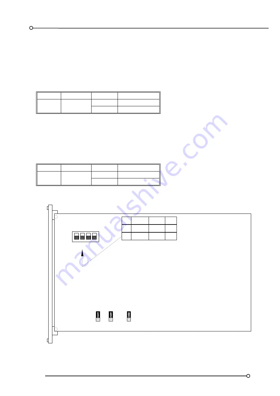
1 2 3 4
SW1
OFF
ON
LK11 LK10
LK9
ON
OFF
ON
OFF
24V
110V
CONTACT
VOLTAGE
POWER
FAIL
1
DE-EN
EN
2
DE-EN
EN
OFF
ON
SW1-
HORN B
HORN A