background image


2


IMPORTANT SAFETY INSTRUCTIONS

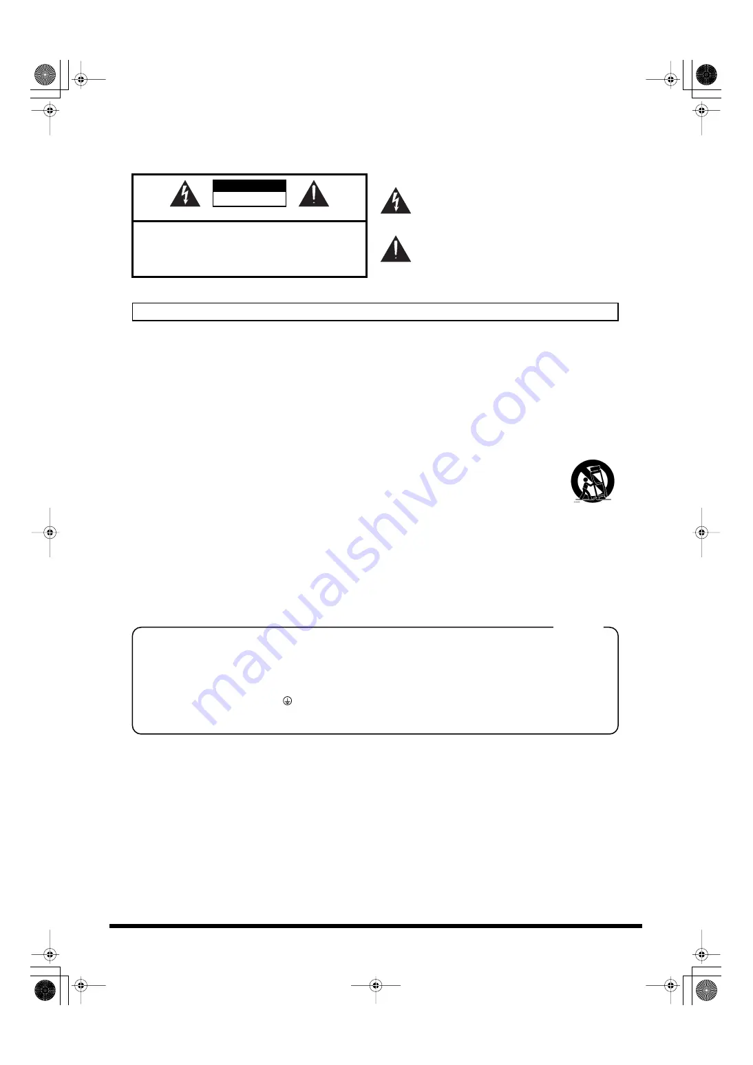
CAUTION

RISK OF ELECTRIC SHOCK

DO NOT OPEN

ATTENTION

: RISQUE DE CHOC ELECTRIQUE NE PAS OUVRIR

CAUTION

:   TO REDUCE THE RISK OF ELECTRIC SHOCK,

DO NOT REMOVE COVER (OR BACK).

NO USER-SERVICEABLE PARTS INSIDE.

REFER SERVICING TO QUALIFIED SERVICE PERSONNEL.

The lightning flash with arrowhead symbol, within an 
equilateral triangle, is intended to alert the user to the 
presence of uninsulated “dangerous voltage” within the 
product’s enclosure that may be of sufficient magnitude to 
constitute a risk of electric shock to persons.

The exclamation point within an equilateral triangle is 
intended to alert the user to the presence of important 
operating and maintenance (servicing) instructions in the 
literature accompanying the product.

INSTRUCTIONS PERTAINING TO A RISK OF FIRE, ELECTRIC SHOCK, OR INJURY TO PERSONS.

IMPORTANT SAFETY INSTRUCTIONS

SAVE THESE INSTRUCTIONS

WARNING 

- When using electric products, basic precautions should always be followed, including the following:

1.

Read these instructions.

2.

Keep these instructions.

3.

Heed all warnings.

4.

Follow all instructions.

5.

Do not use this apparatus near water.

6.

Clean only with a dry cloth.

7.

Do not block any of the ventilation openings. Install in 
accordance with the manufacturers instructions.

8.

Do not install near any heat sources such as radiators, 
heat registers, stoves, or other apparatus (including 
amplifiers) that produce heat.

9.

Do not defeat the safety purpose of the polarized or 
grounding-type plug. A polarized plug has two blades with 
one wider than the other. A grounding type plug has two 
blades and a third grounding prong. The wide blade or the 
third prong are provided for your safety. If the provided plug 
does not fit into your outlet, consult an electrician for 
replacement of the obsolete outlet.

WARNING:
IMPORTANT:

As the colours of the wires in the mains lead of this apparatus may not correspond with the coloured markings identifying 

the terminals in your plug, proceed as follows:

The wire which is coloured GREEN-AND-YELLOW must be connected to the terminal in the plug which is marked by the 

letter E or by the safety earth symbol     or coloured GREEN or GREEN-AND-YELLOW.

The wire which is coloured BLUE must be connected to the terminal which is marked with the letter N or coloured BLACK.
The wire which is coloured BROWN must be connected to the terminal which is marked with the letter L or coloured RED.

THIS APPARATUS MUST BE EARTHED
THE WIRES IN THIS MAINS LEAD ARE COLOURED IN ACCORDANCE WITH THE FOLLOWING CODE.
GREEN-AND-YELLOW: EARTH, BLUE: NEUTRAL, BROWN: LIVE

For the U.K.

10. Protect the power cord from being walked on or pinched 

particularly at plugs, convenience receptacles, and the 
point where they exit from the apparatus.

11. Only use attachments/accessories specified by the 

manufacturer.

12. Use only with the cart, stand, tripod, bracket, 

or table specified by the manufacturer, or 
sold with the apparatus. When a cart is used, 
use caution when moving the cart/apparatus 
combination to avoid injury from tip-over.

13. Unplug this apparatus during lightning storms or when 

unused for long periods of time.

14. Refer all servicing to qualified service personnel. Servicing 

is required when the apparatus has been damaged in any 
way, such as power-supply cord or plug is damaged, liquid 
has been spilled or objects have fallen into the apparatus, 
the apparatus has been exposed to rain or moisture, does 
not operate normally, or has been dropped.

WARNING:

 To reduce the risk of fire or electric shock, do not expose this apparatus to rain or moisture.

S-4000D_e.book 2 ページ 2009年5月25日 月曜日 午前11時46分

Summary of Contents for Digital Snake S-4000D

Page 1: ...wer source This unit automatically detects whether a REAC device connected to a REAC port from 3 to 10 is compatible with REAC EMBEDDED POWER If the REAC device is found to be compatible with REAC EMBEDDED POWER this unit automatically supplies power to it Power is not supplied if the device is not compatible Copyright 2009 ROLAND CORPORATION All rights reserved No part of this publication may be ...

Page 2: ...lug does not fit into your outlet consult an electrician for replacement of the obsolete outlet WARNING IMPORTANT As the colours of the wires in the mains lead of this apparatus may not correspond with the coloured markings identifying the terminals in your plug proceed as follows The wire which is coloured GREEN AND YELLOW must be connected to the terminal in the plug which is marked by the lette...

Page 3: ...low any objects e g flammable material coins pins or liquids of any kind water soft drinks etc to penetrate the unit 012a Immediately turn the power off remove the power cord from the outlet and request servicing by your retailer the nearest Roland Service Center or an authorized Roland distributor as listed on the Information page when The power supply cord or the plug has been damaged or If smok...

Page 4: ...lation 102b Always grasp only the plug on the power supply cord when plugging into or unplugging from an outlet or this unit 103a At regular intervals you should unplug the power plug and clean it by using a dry cloth to wipe all dust and other accumulations away from its prongs Also disconnect the power plug from the power outlet whenever the unit is to remain unused for an extended period of tim...

Page 5: ... it inside an enclosed vehicle or otherwise subject it to temperature extremes Excessive heat can deform or discolor the unit 355b When moved from one location to another where the temper ature and or humidity is very different water droplets condensation may form inside the unit Damage or malfunction may result if you attempt to use the unit in this condition Therefore before using the unit you m...

Page 6: ...ng the Power Off 9 About Placement 10 Important Notes When Installing 10 Cooling fan Intake Port and Ventilation Port 10 When Installing in a Rack 10 Using the REAC Connector Covers 11 Attaching the Rubber Feet 11 Notes to Observe in Using the REAC System 12 Concerning REAC Cables and Their Handling 12 System Connection Example 13 Connecting the S 4000D to a V Mixing System 13 Connecting the S 400...

Page 7: ...K ACT Indicators These indicate the status of the ports The indicators function as follows POWER Indicator Powering up the unit makes the POWER indicator light up POWER Switch This switches the power on and off Front Panel Status Indicator Red POWER Green LINK Yellow ACT With nothing connected Off Off Off When supplying power to a REAC EMBEDDED POWER device Lit When enabled for transmission Lit Li...

Page 8: ...cord here Secure the power cord with the cord clamps p 9 to prevent accidental disconnection of the cords Air Intake Vents Cooling Fan Exhaust Vents The S 4000D contains cooling fans that prevent the unit from overheating The air intake vents provide fresh air for the cooling fans and the fans expel hot air through these vents Clean away any buildup of dust in the intake port or ventilation port u...

Page 9: ...r to the peripheral devices REAC devices compatible with REAC EMBEDDED POWER may have no power switch In such cases the power is switched on automatically when the device is connected to the unit 1 Turn off the power to the peripheral devices 2 Set the POWER switch on the unit s front panel to OFF to switch off the power If you need to turn off the power completely first turn off the POWER switch ...

Page 10: ...e S 4000D in sealed type rack mounts As this type of rack does not permit heated air within the rack to be expelled the heated air is drawn into the S 4000D as a result thus preventing adequately efficient cooling If the rack s rear panel is not removable ensure that a ventilation port or exhaust fan is provided at the top of the rack s rear panel to expel any accumulated heat If the S 4000D is mo...

Page 11: ...r feet when not rack mounting the unit Peel off the backing from the double sided adhesive tape on the rubber feet and attach the feet at the points indicated in the figure below Using the REAC Connector Covers Attaching the Rubber Feet Remove the REAC connector covers if you are using REAC cables with EtherCon type connectors Take care not to lose the REAC connector covers removed at this time S ...

Page 12: ...ernet Category 5 standard No single cable should be longer than 100 meters Do not use cables with cut or torn coverings Do not subject cables to undue stress Do not wind or bend cables such that the radius of the turn is 25 mm or less and do not double cables over Do not bind cables tightly into bundles Concerning REAC Cables and Their Handling To maintain the transmission quality of REAC digital ...

Page 13: ... REAC cables SC W20F SC W100S W100S R sold separately Connecting the S 4000D to a V Mixing System REAC A port REAC B port M 400 FOH M 48 x 8 2 S 4000D REAC port 1 Keyboard Guitar Bass Lead Vocal Drum 16 channels of audio input S 1608 Slave REAC device 8 channels of audio output Front speakers 8 channels of audio output S 1608 Slave REAC device 16 channels of audio input Vocal 1 Vocal 2 Vocal 3 REA...

Page 14: ... an Analog Mixer System S 4000D S 1608 Master REAC device Computer Analog Digital Mixer REAC port 1 or 2 M 48 x 8 Keyboard Guitar Bass Lead Vocal Drum Serial port Vocal 1 Vocal 2 Vocal 3 4 5 6 7 8 9 10 REMOTE connector RS 232C cable REAC port INPUT connector 1 16 REAC cable or Cat5e Ethernet cable REAC port 3 REAC cable or Cat5e Ethernet cable You ll need to install the S 4000 RCS version 2 0 or l...

Page 15: ...10 POWER Blue x 1 Power Supply AC 115 V AC 117 V AC 220 V AC 230 V AC 240 V 50 60 Hz Power Consumption 2 2A AC 115 V AC 117V 1 2A AC 220 V AC 230 V 240 V At Maximum REAC EMBEDDED POWER Dimensions 482 0 W x 285 0 D x 87 8 H mm 19 W x 11 1 4 D x 3 1 2 H inches Weight 4 2 kg 9 lbs 5 oz Operation Temperature 0 to 40 degrees centigrade 32 to 104 degrees Fahrenheit Accessories Power Cord x 1 REAC Connec...

Page 16: ...stallation If this equipment does cause harmful interference to radio or television reception which can be determined by turning the equipment off and on the user is encouraged to try to correct the interference by one or more of the following measures Reorient or relocate the receiving antenna Increase the separation between the equipment and receiver Connect the equipment into an outlet on a cir...

Page 17: ...i 1 535500 Gheorgheni ROMANIA TEL 266 364 609 BRAZIL Roland Brasil Ltda Rua San Jose 211 Parque Industrial San Jose Cotia Sao Paulo SP BRAZIL TEL 011 4615 5666 Other CENTRAL LATIN AMERICA Roland Systems Group U S 425 Sequoia Drive Suite 114 Bellingham Washington 98226 USA TEL 360 594 4282 AUSTRIA BELGIUM FRANCE GERMANY HOLLAND LUXEMBOURG PORTUGAL SPAIN SWITZERLAND Roland Iberia S L Paseo García Fa...

Reviews: